Just an update: Daniel was so very helpful in repairing my board and sending it back to me, it was one faulty Fet creating the offset. 
The dac is fed by a Salas shunt for the 5V, although it is not optimal because of the following 3.3 and 3.6 regs for clock and Chip. And source is WaveIo, also fed by 2 shunts for the 2 required 5V and a Linux netbook with Low Latency kernel.
After some burn in of 2 or 3 days this thing is realy good, slightly leaning towards the warm side to my surprise, very un-digital, if you know what I mean. And at the same time very precise, dynamic with great bass and good timing. Put it in a nice case, and you can sell at your Hifi dealer for 2000 quid...
I like it better than my tube/transformer output AD1865 Dac, which is maybe more romantic, but for the rest clearly inferior. Probably also the I2S connection is a reason for this improved picture, the other Dac has still SPDIF.
Great work from Ron and Daniel, thanks again!
And I am thinking about some more shunt regs for the 3.3, 3.6 and +/-15 Volt
Ah, one more thing: after a while the power supply board gets really warm on the +-15v part, and the capacitors are also very warm to almost hot. So I would recommend 2 small finger heatsinks for the 317/337 regs to avoid heatsinking through the boards ground plane.
Last edited:
Thanks Jogi for the feedback
I'd like to second the recommendation for propper heatsinking. While it actually works without if you draw only low current (e.g. one curryman DAC) it is definately better to keep things cool
There also seems to be some variance with the transformers. While my PSU stays quite cold the Version from a friend gets significantly hotter (still within spec though).
And finally a remark wrt the zener diodes: When I did my first few builds (actually me and friends set up about 10 PSUs incl. a group buy of the components) the ZF 13 ordered from Reichelt showed right about 13V which gives about 14.25V at the PSU output. The actually delivered zeners seem to have a higher voltage (arround 13.9V, still within spec) and thus the output voltage of the PSU will be ~15.15V. This is perfectly OK for the DAC. I just want to avoid confusion since the assembly guide says 14.25V
kind regards and happy listening, Daniel
curryman DAC with RPi
Hi all,
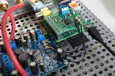
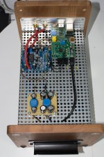
just a small upgrade: today I managed to do some first tests with my small I2S isolator board for the RPi. It stacks directly on the Pi and provides isolated I2S outputs on either a pin header (same layout as the curryman DAC I2S header) or U.FL connectors. I used the latter for my network player setup.
Still have to upgrade the power supply (currently crap SMPS, thus the supply line filters) but it sounds already quite good
have a nice sunday, Daniel
PS: I will do some more tests and provide the boards to some friends and when everything works well I will try to make them available somehow (I will not do a GB but maybe someone else...).
Hi all,
just a small upgrade: today I managed to do some first tests with my small I2S isolator board for the RPi. It stacks directly on the Pi and provides isolated I2S outputs on either a pin header (same layout as the curryman DAC I2S header) or U.FL connectors. I used the latter for my network player setup.
Still have to upgrade the power supply (currently crap SMPS, thus the supply line filters) but it sounds already quite good
have a nice sunday, Daniel
PS: I will do some more tests and provide the boards to some friends and when everything works well I will try to make them available somehow (I will not do a GB but maybe someone else...).
Attachments
Last edited:
Hi all,
just a small upgrade: today I managed to do some first tests with my small I2S isolator board for the RPi. It stacks directly on the Pi and provides isolated I2S outputs on either a pin header (same layout as the curryman DAC I2S header) or U.FL connectors. I used the latter for my network player setup.
PS: I will do some more tests and provide the boards to some friends and when everything works well I will try to make them available somehow (I will not do a GB but maybe someone else...).
Looking very nice indeed. I was about to ask how would it be possible to use I2C with it until I noticed that there is a separate I2C pinout at the edge of the pcb. Now I want to have one...
Hi all,
just a small upgrade: today I managed to do some first tests with my small I2S isolator board for the RPi. It stacks directly on the Pi and provides isolated I2S outputs on either a pin header (same layout as the curryman DAC I2S header) or U.FL connectors. I used the latter for my network player setup.
Nice! I like the way the isolator is stackable. That will allow the whole combination to be housed in a pretty small case (which my wife will like very much...)
Looking very nice indeed. I was about to ask how would it be possible to use I2C with it until I noticed that there is a separate I2C pinout at the edge of the pcb. Now I want to have one...
There is indeed I2C available at a pin header but it is not isolated! So if you want galvanic isolation you'd need to add an I2C isolator.
kind regards, Daniel
Daniel,Hi all,
just a small upgrade: today I managed to do some first tests with my small I2S isolator board for the RPi. It stacks directly on the Pi and provides isolated I2S outputs on either a pin header (same layout as the curryman DAC I2S header) or U.FL connectors. I used the latter for my network player setup.
Still have to upgrade the power supply (currently crap SMPS, thus the supply line filters) but it sounds already quite good
have a nice sunday, Daniel
PS: I will do some more tests and provide the boards to some friends and when everything works well I will try to make them available somehow (I will not do a GB but maybe someone else...).
I am not an expert on the Rpi, but does this setup work like a USB dac? That means the Rpi plays a role as USB-i2s?
Well, there's now a new version of the Raspberry Pi: B+. Just ordered one from the Amazon. It has more GPIO pins on the row on the edge but the other connection for I2S seems to be missing. Gotta investigate this when I get the hardware at hand.
I found the answer: the I2S is incorporated into that new 40 pin header instead of the old separate header. So it will need a new layout for that I2S isolator...
I found the answer: the I2S is incorporated into that new 40 pin header instead of the old separate header. So it will need a new layout for that I2S isolator...
Don't think so. Seems to me the isolator is already using the 8-pin P5 header on the Raspberry Pi, which outputs i2s directly. See RPi-DAC - High Quality DAC
Is that correct Daniel?
The isolator board fits to RPi model B and indeed uses the 8-pin P5 header for I2S Signals.
However tuo is referring to the new B+ model of the RaspberryPi and this would indeed require a new layout. But to be honest I do not plan to do a new layout at the moment since model B will still be available and for this application I don't see any significant benefit in using model B+. After all it's my hobby...
kind regards, Daniel
The isolator board fits to RPi model B and indeed uses the 8-pin P5 header for I2S Signals.
However tuo is referring to the new B+ model of the RaspberryPi and this would indeed require a new layout. But to be honest I do not plan to do a new layout at the moment since model B will still be available and for this application I don't see any significant benefit in using model B+. After all it's my hobby...
kind regards, Daniel
Ah, now I see. That is news to me, interesting..
The new B+ model was officially released yesterday, so it should be news to about anybody else than people developing the Pi hardware.
A little explanation about the hassle: I have an idea for a network player having a hardware UI and for that purpose I need more GPIO than the original model B has and the B+ does offer. So in the end I most likely end up doing the development with the B+ and then backtracking it to B with a GPIO extender on the I2C bus or redoing the curryman isolator for the new layout as I'd like to use the curryman DAC for the player.
But this is enough clogging for this thread, I'll start my own, when I have something more concrete to talk about.
Temperature buildup
I too have noticed the boards run quit warm even when loaded with just one dac. Put a few together in an unvented box and the temperature begins to rise significantly. I originally had one 15v board with small heatsinks driving 2 dacs and another 15v board without heatsinks driving a single dac plus a 5v board. The ambient temp in the case reached 50 degrees after about 30 mins. The lm317 on the psu with heatsinks (driving 2 dacs) reached 62 degrees and the lm317 without heatsink driving the single dac reached 85 degrees.
I've now added small heatsinks to all the regulators and getting readings of 55 to 62 degrees.
The sound quality of the curryman dacs driven by these PSU is excellent - very impressive Daniel!
Gordon
Thanks Jogi for the feedback
I'd like to second the recommendation for propper heatsinking. While it actually works without if you draw only low current (e.g. one curryman DAC) it is definately better to keep things cool
There also seems to be some variance with the transformers. While my PSU stays quite cold the Version from a friend gets significantly hotter (still within spec though).
I too have noticed the boards run quit warm even when loaded with just one dac. Put a few together in an unvented box and the temperature begins to rise significantly. I originally had one 15v board with small heatsinks driving 2 dacs and another 15v board without heatsinks driving a single dac plus a 5v board. The ambient temp in the case reached 50 degrees after about 30 mins. The lm317 on the psu with heatsinks (driving 2 dacs) reached 62 degrees and the lm317 without heatsink driving the single dac reached 85 degrees.
I've now added small heatsinks to all the regulators and getting readings of 55 to 62 degrees.
The sound quality of the curryman dacs driven by these PSU is excellent - very impressive Daniel!
Gordon
Just to demonstrate the versatility of the Curryman PS boards, here's one I built to power the tube filaments in a hybrid headphone amp I'm working on (using an Erno Borbely circuit).
Each tube filament draws 330mA so the power supply is working quite hard, hence the large heatsinks (which get quite warm but not so as I cannot touch them). The transformer gets warm too, but not excessively so. I was going to measure the temperatures but my infra-red non-contact thermometer battery has died so later.
Onwards!
Ray
An externally hosted image should be here but it was not working when we last tested it.
Hi All,
I'm just beginning to put together my Curryman DAC, I'm using a DSP mini streamer to feed the DAC and will power it off of the 5V output on the Curryman PSU. I''ll also be using the streamer to handle both optical and coax spdif inputs via a selector switch. One question though, because of space constraints I'm thinking of stacking the two torroid transformers that I'm using to power the PSU. Does anyone think that this will cause problems ?
Thanks,
PJN
- Status
- This old topic is closed. If you want to reopen this topic, contact a moderator using the "Report Post" button.
- Home
- Group Buys
- GB for currymanDAC & PSU Boards