.......
I had made a copy of another BOM that had the bleed resistors in the wrong spot and I saw some photos over ar AK that also had the resistors in the wrong location....
Thanks again.
Just a side note to this topic. Be sure to use the most current guide from Cviller(rev .6) I built my power supply board from the initial guide. luckily I used a variac, as those resistors were in the wrong place.
jim
Thanks Jim...
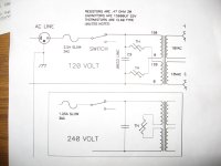
When I look at the Nelson Pass owners manual, the Power supply is connected to the chassis ground via a thermistor.
Yet from what I can determine Christian's wiring diagram does not connect the PS to chassis gnd.
I have also seen diagrams with "star ground" configurations where even the
-ve speaker terminal is connected to the star ground as well as the PS and
input signal ground.
Will all of the above work in the same way are these other methods for special applications??
Thanks Jim...
When I look at the Nelson Pass owners manual, the Power supply is connected to the chassis ground via a thermistor.
Yet from what I can determine Christian's wiring diagram does not connect the PS to chassis gnd.
I have also seen diagrams with "star ground" configurations where even the
-ve speaker terminal is connected to the star ground as well as the PS and
input signal ground.
Will all of the above work in the same way are these other methods for special applications??
I think Christian left the thermistors off of the power supply board. The thermistor is to help prevent a ground loop. I plan to wire it in according to Nelson's circuit. I think he has pretty good judgement.
I think Christian left the thermistors off of the power supply board. The thermistor is to help prevent a ground loop. I plan to wire it in according to Nelson's circuit. I think he has pretty good judgement.
I think they are Varistors.
Ummmm, According to what I read the Varistor is there to prevent (slow down) blowing a fuse when the torrid transformer starts up. In which case there 2 of them.
or are you referring to the thermistor on the Mosfet? Which is used for stability (thermally)
Ron
I guess my real question is , does the power supply need to be connected to chassis ground??
It appears that some do and others don't make this connection...
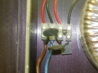
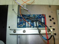
These pics show how I built my F5.
The first pic is the thermisters
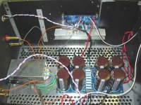
the second pic shows the 2 ground wires from power supply pcb
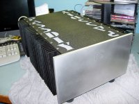
the third completed
I figured that once it worked I would go back and shorten and generally clean up the wiring, however it sounds so good I have just been listening.
")
I would think it's right, because the amp is completely silent with volume at max and no source playing. I connected the power supply board to ground.
Attachments
ground everything
For your safety both chassis and power supply need to be grounded. The chassis directly to safety earth (the 3rd ground pin from the power connection) and the power supply to either safety earth or chassis (since the chassis is/should be connected to safety earth it's the same thing) via a cl-60 or other disconnecting circuit.
As far as the 2.2k 3Watt resistors on the power supply, they are optional, used to drain the caps on power down for safety. If you have speakers connected they are not necessary and perhaps sounds better without them. The R3&R4 2.2k resistors do not need to be 3Watt.
I guess my real question is , does the power supply need to be connected to chassis ground??
It appears that some do and others don't make this connection...
For your safety both chassis and power supply need to be grounded. The chassis directly to safety earth (the 3rd ground pin from the power connection) and the power supply to either safety earth or chassis (since the chassis is/should be connected to safety earth it's the same thing) via a cl-60 or other disconnecting circuit.
As far as the 2.2k 3Watt resistors on the power supply, they are optional, used to drain the caps on power down for safety. If you have speakers connected they are not necessary and perhaps sounds better without them. The R3&R4 2.2k resistors do not need to be 3Watt.
These pics show how I built my F5.
the third completed
Is that a hunk of u-channel alum. to clamp down the outputs?
That would give some extra finned cooling. How did you bolt it?
Through the mosfet holes or not.
Is that a hunk of u-channel alum. to clamp down the outputs?
That would give some extra finned cooling. How did you bolt it?
Through the mosfet holes or not.
Yes, dimensions are 3/4" wide x 1" tall x 1/8" thickness.
here is a pic of the bolts, they are 10-32, and are on both sides of the mosfet.
jim
Attachments
I'm afraid I have just run out of boards. I can order another batch if there is a interest for more F5 boards.
Plz write here or to my email if you are interested.
Christian,
Could you please ask this same question on Nelson's F5 thread, probably get more hits/replies there.
Ron
just being selfish, I may have killed another one myself...............I'm usually not this hard on boards.............honest!
I think there will be. I might make the boards longer - any objections?
A couple inches longer would be great.
My plan is to double the distance between the mosfets (it is 8 cm now).
Christian,
Wonderful Idea to increase the distance between mosfets.
increased cooling area.
Yeah.
Ron

- Status
- This old topic is closed. If you want to reopen this topic, contact a moderator using the "Report Post" button.
- Home
- Group Buys
- Gb: F5 Pcb