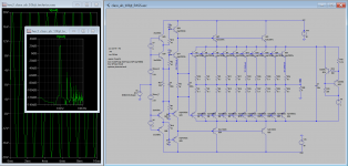
Damir check your eMail, send you the schematic of the test circuit.
C3 serves to speed the switching off of the output transistors, a 220nf is enough.
Nelson Pass has many years ago invented a circuit that can overcome the problem of using high bias current, in this example the bias current is 1A but the amplifier only waste a bit more than 25w per channel without the pass circuit the amplifier will dissipate a bit more than 100w or 200w in a stereo amplifier.
Also the .asc file if someone want to further investigate the concept.
Attachments
Last edited:
Pawel this is only a test circuit to demonstrate a concept, in a pratical circuit the output transistors should have base resistors.
edit: and the pre_drivers transistors should also have base resistors and caps to ground as the drivers transistors have, to slow the circuit.
edit: and the pre_drivers transistors should also have base resistors and caps to ground as the drivers transistors have, to slow the circuit.
Last edited:
Damir check your eMail, send you the schematic of the test circuit.
C3 serves to speed the switching off of the output transistors, a 220nf is enough.
Nelson Pass has many years ago invented a circuit that can overcome the problem of using high bias current, in this example the bias current is 1A but the amplifier only waste a bit more than 25w per channel without the pass circuit the amplifier will dissipate a bit more than 100w or 200w in a stereo amplifier.
Also the .asc file if someone want to further investigate the concept.
Segio, you used 100 uF for C3 in your previous schematic, that is why I asked.
I will simulate your OPS and let you know.
UltimateX86, if we omit the emitter resistors from the output the distortion will be lower but the problem is that in doing so the stage becomes thermally unstable, so in practice those resistors can not be omitted.
I really don't recommend the Sziklai pair for class AB, because the distortion at the crossover region is worst that what can be achieve with the darlington pair. In class A the Sziklay is more linear than the darlington, but again I personally don't recommend class A (just ecological issues of course).
Maybe we could use darlington + CFP
THD20K 1W : 0.004% and 0.005% 100W with low bias
https://sites.google.com/site/opampbasedamp/Brute.png
do you know how using Onsemi Thermaltrak bias ?
https://sites.google.com/site/opampbasedamp/SLCLT.png
https://sites.google.com/site/opampbasedamp/SLCLT.png
do you know how using Onsemi Thermaltrak bias ?
https://sites.google.com/site/opampbasedamp/SLCLT.png
I used it in standard EF triple, with the diamond I am not sure, never tried it yet.
Hi Damir,
It seems that the genius dr malcolm hawksford have already use the same type of configuration that I use in my Error correction (in 1983)
so if you want, you can put here the circuits that we made.
Thank you Sergio, I opened a new thread for NGNFB class B power amp here: http://www.diyaudio.com/forums/solid-state/260308-gainwire-ngnfb-classb-poweramp.html#post4018576
BR Damir
- Status
- This old topic is closed. If you want to reopen this topic, contact a moderator using the "Report Post" button.
- Home
- Amplifiers
- Solid State
- GainWire-CLASS-A-poweramp NGFB