Bricolo said:
I can have oscillations, since I still have no casing
but variable oscillations, depending of the volume pot's position, that's really weird
It's not weired, I observed that too in my amps. Put everything in a grounded case and then check again. If you built regular gainclone, or the one according to Thorsten schematic, the circuit is rather stable, but as soon as I connected positive input directly to ground, I had some oscillations untill I grounded the chassiss.
Peter Daniel said:
It's not weired, I observed that too in my amps. Put everything in a grounded case and then check again. If you built regular gainclone, or the one according to Thorsten schematic, the circuit is rather stable, but as soon as I connected positive input directly to ground, I had some oscillations untill I grounded the chassiss.
but did you have variable oscillations, that vary with your volume pot's position? (min at 0 and 100, max at 50) ?
Bricolo,
That behavior is very common. At min volume the input has very low impedance to ground; at max volume the input has low impedance to the source. At mid volume the input has high impedance to both ground and source, which makes it much more vulnerable to induced signals. Shielding of small signal wiring and/or the entire unit may eliminate the problem.
That behavior is very common. At min volume the input has very low impedance to ground; at max volume the input has low impedance to the source. At mid volume the input has high impedance to both ground and source, which makes it much more vulnerable to induced signals. Shielding of small signal wiring and/or the entire unit may eliminate the problem.
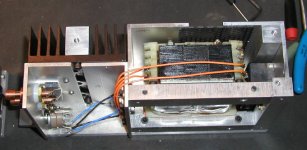
Recently I had a chance to redesign my monoblocks. I removed TDA7294 chips and installed LM3875. I also put there 1000u/50 BG N type caps (2 per channel) with 4.7 BG N bypass right at the chip. I used Caddock 220K feedback resistor and stepped volume control at the input with 3 10K Vishay S102 resistors and 5 positions only. The pot is in series, without connection to ground. I also used Cardas wiring inside.
Initially on a first try the sound was so disappointing that I couldn't believe") But after 2 days the amp is singing indeed. I guess it's BG that needed more time to improve. One mechanical area that was quite critical was a bottom cover on the circuit side. Initially I used 1/4 aluminum plate with a brass spike in a center. The sound was kind of flat and not involving. I took out that plate and placed a piece of 3/4" maple block and the sound open beyond my expectations. Adding another strip of 1/4 acrylic under the wooden block improved it even better.
But after 2 days the amp is singing indeed. I guess it's BG that needed more time to improve. One mechanical area that was quite critical was a bottom cover on the circuit side. Initially I used 1/4 aluminum plate with a brass spike in a center. The sound was kind of flat and not involving. I took out that plate and placed a piece of 3/4" maple block and the sound open beyond my expectations. Adding another strip of 1/4 acrylic under the wooden block improved it even better.
This is the best gainclone I made so far I guess. And this time I keep Fedde happy too as I used stepped volume switcher
Initially on a first try the sound was so disappointing that I couldn't believe
But after 2 days the amp is singing indeed. I guess it's BG that needed more time to improve. One mechanical area that was quite critical was a bottom cover on the circuit side. Initially I used 1/4 aluminum plate with a brass spike in a center. The sound was kind of flat and not involving. I took out that plate and placed a piece of 3/4" maple block and the sound open beyond my expectations. Adding another strip of 1/4 acrylic under the wooden block improved it even better.This is the best gainclone I made so far I guess. And this time I keep Fedde happy too as I used stepped volume switcher
Attachments
Better IC pins?
I think that its great the way you've situated the chip to allow the pins direct proximity to the output binding posts. Can’t make the signal path much shorter than that. Have you considered trying to beef up the pins by laminating copper or silver conductors to them? I cant imagine that the IC pins were designed to do anything another than be tinned conductors.
I was also a little surprised to see the shielded split core transformer. Was there any specific reason you chose this over a torroid?
Ive been getting the house painted so I we can put it on the market and move. Perhaps once this is done I can get back to a more constructive hobby like building some amplifiers.
-Dave
Re: Better IC pins?
The main reason was size and shape and the way it could be mounted. I got those transformers 20 years ago and finally put them to good use. Soundwise there is not much difference than toroids.
The pin from output to binding post is less than 6mm. I might beef it up later. As to the other pins there is no need as everything connects directly at IC's case.
Da5id4Vz said:I was also a little surprised to see the shielded split core transformer. Was there any specific reason you chose this over a torroid?
The main reason was size and shape and the way it could be mounted. I got those transformers 20 years ago and finally put them to good use. Soundwise there is not much difference than toroids.
The pin from output to binding post is less than 6mm. I might beef it up later. As to the other pins there is no need as everything connects directly at IC's case.
Peter Daniel said:This is the best gainclone I made so far I guess. And this time I keep Fedde happy too as I used stepped volume switcher
Very happy now, thanks
Nice clone again. Good idea, the 4.7 uF's close to the IC. I wanted to try that tonight too. Did you already try a 220 k resistor on the +input !? You know, I could be even a bit happier
Fedde
I have been reading these posts for a while... have a couple of questions to be sure I am on track:
1) a multi-turn trim pot (50k was mentioned, could 20k be used?) on the non-inverting input to ground will allow adjustment of dc offset. How does this pot do this? I am trying to understand what it is actually adjusting.
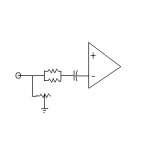
2) instead of using a 50k pot and a 10k 1watt resistor for the input, could 2 20k Vishay S102 (0.6W) in parallel be used with a pot shunted to ground? I attached a picture to show what I mean. This way the signal only passes through the vishay resistors, yet a plain jane pot can be used for volume control. The volume pot only shunts to ground, so it should eliminate the need for a high quality pot, and allow for a much broader adjustment range than a couple position stepped attenuator.
Thanks
1) a multi-turn trim pot (50k was mentioned, could 20k be used?) on the non-inverting input to ground will allow adjustment of dc offset. How does this pot do this? I am trying to understand what it is actually adjusting.
2) instead of using a 50k pot and a 10k 1watt resistor for the input, could 2 20k Vishay S102 (0.6W) in parallel be used with a pot shunted to ground? I attached a picture to show what I mean. This way the signal only passes through the vishay resistors, yet a plain jane pot can be used for volume control. The volume pot only shunts to ground, so it should eliminate the need for a high quality pot, and allow for a much broader adjustment range than a couple position stepped attenuator.
Thanks
Attachments
Mach_Y said:
2) instead of using a 50k pot and a 10k 1watt resistor for the input, could 2 20k Vishay S102 (0.6W) in parallel be used with a pot shunted to ground? I attached a picture to show what I mean. This way the signal only passes through the vishay resistors, yet a plain jane pot can be used for volume control. The volume pot only shunts to ground, so it should eliminate the need for a high quality pot, and allow for a much broader adjustment range than a couple position stepped attenuator.
I tried it, but there is no really good regulation with 50k pot, as the pot should be in a range of 300ohms to make fine adjustments with volume.
As to the first question, depending what configuration you are using, but when the other input is connected through resistor to ground (same value as feedback resistor?) the offset should be less than 10mV and this is perfectly fine, without need for additional trimpot. I'm connecting the other input directly to ground and offset is less than 30mV. I understand tha offset issues are more important when bridging and paralleling amps and then the pot might be required.
Peter Daniel said:
I tried it, but there is no really good regulation with 50k pot, as the pot should be in a range of 300ohms to make fine adjustments with volume.
I thought your schematic used a 50k pot on the input... I got the schematic from the main post of yours (very long one on gainclones) around post 890 or so. If you don't use this, then a 300 ohm pot should be used for volume control instead? That just doesn't seem right to me. Could you post what you did for your latest version on volume control where you mentioned you used 3 S102 Vishay resistors for a stepped attenuator? What would the input stage look like if I did not want volume control on the amps at all?
Peter Daniel said:
As to the first question, depending what configuration you are using, but when the other input is connected through resistor to ground (same value as feedback resistor?) the offset should be less than 10mV and this is perfectly fine, without need for additional trimpot. I'm connecting the other input directly to ground and offset is less than 30mV. I understand tha offset issues are more important when bridging and paralleling amps and then the pot might be required.
I realize with good parts that that the offset is minimal. The configuration is yours mentioned above. I know the trimpot is not required, but I assume it couldn't hurt, right?
Thanks again
Mach_Y said:
I thought your schematic used a 50k pot on the input... I got the schematic from the main post of yours (very long one on gainclones) around post 890 or so. If you don't use this, then a 300 ohm pot should be used for volume control instead? That just doesn't seem right to me. Could you post what you did for your latest version on volume control where you mentioned you used 3 S102 Vishay resistors for a stepped attenuator? What would the input stage look like if I did not want volume control on the amps at all?
50k pot will not work with a circuit you suggested, when fixed 10K resistor is in series and 50k variable pot between input to ground. In that case you need a pot around 300ohm to get proper control range. If you are using 50K pot in regular arangement (as on my older schematic) it works fine. What I did recently in my monoblocks, I set it up in a way that I have either 10k or 20k, 30k, 40k in series with input (by adding consequentive 10K Vishay resistors), without any resistance connection to ground. I have only 5 settings on my switch, but for now i like this simple arrangement as I don't listen very quiet
It is usually no extra resistor at all, or only first one. I would say that might be the best pot there is, if you are not picky about perfect volume level.Mach_Y said:I realize with good parts that that the offset is minimal. The configuration is yours mentioned above. I know the trimpot is not required, but I assume it couldn't hurt, right?
Actually the gainclone circuit is very sensitive to all the parts used and the pot might indeed hurt the sound. But I didn't try it, so can't comment for sure. But I prefer to keep things simple.
Mach_Y said:
I realize with good parts that that the offset is minimal. The configuration is yours mentioned above. I know the trimpot is not required, but I assume it couldn't hurt, right?
Thanks again
I would say that it's definitely worth trying connecting the non inverting i/p direct to earth. I recently shorted out my 9.5K ohm resistors to acheive this and to my ears it was a big improvment.
others here say it's important to get both channels with matched dc offset - I wonder I they have tried the zero ohm option ?
mike
Yesterday, I poked the soldering iron into my GC monoblocs again and put an 18K to ground on the inverting input and a 22K on the non-inverting input as shown HERE
The monblocs are as identical as I can make them but one now has a DC offset of 0.4mV and the other has 4.5mV! I'm not sure what is causing the difference although it is not large enough (IMHO) to matter too much.
I have been in correspondence with Mark Henessey about this mod and he said the following:
--------------------------------------------------------------------------------
On the face of it, connecting an extra resistor between a virtual earth and a "real" earth seems like a strange thing to want to do, as it will have no effect. But it should equalise the resistance seen by the two inputs, so that the bias currents develop equal offset voltages, hence no overal DC offset because the voltage difference between + and - is nothing. Actually 220K || 22K is
20K, not 18K
It worries me slightly - the inverting input is only help at 0V (virtual earth) by global feedback - therefore at high frequencies the virtual earth becomes less ideal. Easy to see with a scope. So, this resistor might soften the higher frequencies - perhaps not a bad thing for some people... Also, the sound during clipping might be affected.
-------------------------------------------------------------------------------
Indeed, the higher frequencies are a little softer, an in some ways that makes the sound more preferable although I would need to switch back and forward a few times to decide finally.
I will also try the arrangement with the 50K trimpots to ground on the inverting input.
Peter Daniel said:It offers somewhat thick and veiled sound, as if I were looking for something through a thin mist, more like a haze.
Too much black gate ?

I would say that it's definitely worth trying connecting the non inverting i/p direct to earth. I recently shorted out my 9.5K ohm resistors to acheive this and to my ears it was a big improvment.
Mike, what are using on the inverting input to ground? And what is the DC offset with the non-inverting to ground connection shorted?
'Mike, what are using on the inverting input to ground?'
before I was using approx 9.5K tiny presision surface mount from RS as recommended to me by thorston.
now I am using a piece of ( cat 5 ) copper wire
'And what is the DC offset with the non-inverting to ground connection shorted?'
one is about 10mV the other about 30mV
but it sounds great
cheers
mike
- Status
- This old topic is closed. If you want to reopen this topic, contact a moderator using the "Report Post" button.
- Home
- Amplifiers
- Chip Amps
- Gainclone monoblocks