post29 and post30 pics are useful. but confusing.
Post29 pic 1.
Shows the typical ground symbols. This is completely misleading. The grounds are not all the same.
post20 pic 2.
is almost correct. The first 5 connections starting at the input are all signal ground.
the last on the right and below are NOT Signal Ground. The PSU is Power Ground. The last is Safety Earth.
Add a resistor between Power Ground and Signal Ground.
Add a disconnecting Network between Power Ground and Chassis.
Connect the Mains green/yellow or third wire to Chassis.
Add in the local decoupling and the Output Zobel. These all connect together. Connect them to Power Ground.
Connect the Speaker Return to Power Ground.
Inside the PSU you will have a pair of smoothing capacitors to give your roughly smoothed DC supply. The link between the smoothing capacitors is very NOISY. DO NOT connect any audio circuit to this link. This is PSU Zero Volts
Instead, take ONE wire along with the +ve and -ve, as a three wire twisted triplet to the amplifier and connect that ONE wire to Power Ground.
Post29 pic3
shows all the Chassis and Safety Earth and PSU Noisy link and Power Ground and signal Ground connected as a common reference Star Ground. this is very likely to give a noisy outcome.
DO NOT do it as pic3 !
post30
shows the transformer centre tap connected to the wrong end of the smoothing caps.
The centre tap MUST be connected to the left side of the capacitor Zero Volts link.
The Output from the Zero volts link MUST come from the right hand end just like the +ve and -ve Outputs.
Bentsnake has been told that post30 pic is wrong.
Yet he repeatedly posts the same wrong pic.
Last edited:
.
Factory engineers with a van full of test instruments have been known to spend days looking for a 60Hz hum. Which tells us that sometimes there's a quick and easy solution, sometimes not.
<< I am so frustrated and disappointed >>
As anybody would be. Again I suggest cutting your losses, throw the whole thing away and start over. You paid 20 bucks for experience, which is relatively cheap.
<< power supply is not snubberized, so stays on for 3-4 secs after being switched off >>
It should stay on, this is your enormous capacitor bank discharging. Don't worry about "snubberizing," umpteen million amps are working fine without such niceties.
I get what you mean: it sounds fine with the AC line disconnected. But this does not necessarily point to a power supply problem. Might be, might not be. I personally remain more interested in your input circuit.
Complete change of subject. You need to understand this: things are going on in there that you don't know about. If you really want to know what's happening inside a circuit, then see you in 6 or 7 years when you have your EE master's degree.
This is why shadetree techs are wise to stick with the tried and true, which especially means sticking with the factory circuit. This is how "chip amps" came into existence in the first place. Somebody ran across a data sheet, looked at it, said, "Jeeze, am I really paying $300 for 4 resistors and 3 capacitors?!" and away we go.
Here's what I suggest: first and foremost forget that you have two amps. Concentrate on getting one, and only one, working.
This means disconnect the second amp, and "disconnect" means everything. Everything = everything.
Now concentrate on your input circuit. This is because if your input is screwed, how is anything down the line going to be right? Hint: it's not.
Two channels (left and right) are coming in from whatever player you're using. Are the two channels connected in any way? They must be kept separate. I'm guessing they share a single ground (the shield), and that's fine. Or...are you, in fact, using a shielded connecting cable (a "patch cord")?
What is your input circuit? That is, how does the channel you're using (left or right) get from the patch cord to pin 10 of the LM3886?
The input ground (shield) needs attention. If it's connected to the chassis at an input jack, then that can be a source of distortion or noise. Is the input grounded directed to a central ground point?
Gotta watch those inputs.
.
.
<< Connect the Speaker Return to Power Ground, etc >>
Or maybe not. Possibly of interest:
Grounding Principles - The Signal - Archives - TI E2E Community
.
<< Connect the Speaker Return to Power Ground, etc >>
Or maybe not. Possibly of interest:
Grounding Principles - The Signal - Archives - TI E2E Community
.
.
I feel called upon to speak with great wisdom. But I can't do that, so I'll say this instead.
Mohitkmittal, understand that electrons don't conveniently do as we wish they would all the time, so all circuits are compromises. The questions is always "compromise in which direction"?
Quite often it just doesn't matter, one way is as good as another. Ask 6 engineers, you'll get 6 different answers, usually said as, "I wouldn't have done it that way, but that looks OK." So now opinion enters in.
So here's some poor guy asking for some help, and suddenly 6 different self-appointed experts (not engineers) are screaming their opinions in his ear. So who's a guy supposed to believe?
Boy, ain't that life in a nutshell. What I do is scout around, look for some kind of average or common denominator, apply my own judgment, and after that, hey, you take your shot. If that doesn't work, regroup and try something else. Yep, life.
.
Mohit
Maybe you should cut your losses and pick up some nice PCBs ready to go.
Here's one, a good design by BrianGT. You may feel a little less accomplished but maybe a bit wiser. http://chipamp.com/product/non-inverting-lm3886-stereo-pcb-set/
Just stuff the boards and hook up the wires, can't get simpler than that and you'll have a working amplifier.
If you need to 'learn how to fish', it will just take time and patience. Break the circuit down into various elements. Get one working channel, without hum and noise. The posters here are only trying to help.
There are a lot of ways to get a reliable and noise free circuit, but it is not possible without careful layout. Lead dress is really important when it comes to P2P builds, as all the exposed components can and do pick up noise and interference.
One good rule to understand, since you're an engineer, is that there is no component through which some current does not pass, and that some emission is received and transmitted every time this happens. Think of each current, and try and separate their paths as well as physically possible. Where it is unavoidable, try and cross them at right angles. Do not run high current paths near low current ones, for example input and power or output near the same physical location or the same path.
It is quite possible to get a good P2P build. Look up the old chipamp threads, I learnt form Peter Daniels' posts and it has served me well. I do not build any chipamps any more and if I do I simply import some Chinese PCBs and build on those. Only for critical applications and custom builds do I go back to P2P because it is a painful exercise, and a difficult one to get right.
If you would want to persist, knock your build down to mono. Get that done. Stereo grounding is far more complicated due to the ground loop of the input cable, and can be done after you verify correct operation (not conditional).
Good Luck.
Thanks all, again, for all your suggestions and help. I will try the suggested techniques and let you know what I find.
@Andrew: I will add a Zobel and let you know what I find. Thanks also for the grounding tips.
@bentsnake: The input circuit I am using is the same as the one on the parallel schematic. I also just have one chip per channel, and only two channels. The input signal ground is common and goes into the audio ground of the star ground. I have 1uF poly caps for AC coupling.
I know I am not as knowledgeable or as experienced in this as any of you guys, but my circuit was working completely fine before I tried to parallel the chips. Had the same layout too. I don't know why it is not working now. I completely understand the importance of short signal leads, good layout, etc., but frankly all I want is a good sounding amp, not a perfect sounding amp. Even in my present circuit, there is very less DC offset, it is <5mV. I don't know how or why it increases to 100+mV after a certain volume now - did not do this before.
@Sangram, to your point, mono is working very well. There is no DC offset. There is a slight constant high freq noise, but it is not audible once music is played. Both channels work fine in mono, any volume, any sort of music. DC offset in stereo is also non-existent, until a certain volume level is reached. Each channel also sounds very good generally, very open and deep soundstage, no interference of any sort.
I know that I am probably sounding like an idiot and all believe I need to change the layout - probably that is a solution, but my struggle is that why is something that was working flawlessly before not working now. To everybody's point, especially bentsnake's, something has changed - I can see that, but that is what I am struggling to find.
I will keep everybody posted though, and thanks again for your help.
.
<< I know that I am probably sounding like an idiot >>
No, you sound like a guy confused by conflicting advice from self-appointed experts. Welcome to the wonderful world of forums.
<< all believe I need to change the layout >>
Not me.
<< There is a slight constant high freq noise >>
Feedback accounts for all of your symptoms except the [supposed] ground loop, and maybe that too. Feedback doesn't have to make you run for the volume control, it can be subtle, it can even be supersonic, and you've got it.
Why? At this point who knows. If you've made all the changes that have been advised, surely your board is a mess by now. I personally am still suspicious of your input(s), but my current thinking is to echo your own words, "...my circuit was working completely fine before I tried to parallel the chips."
My thinking is also to echo my own words: go back to Go, and stick with the engineers at the factory, the guys who created the chip in the first place. A lot of people have been explaining to you all about how you're wrong, but the factory guys will steer you right.
.
.
<< ...confusing...misleading...DO NOT...wrong...wrong...wrong...[and a great deal more] >>
This seems to be a case of looking at the pictures, but not actually reading the thread.
All the circuits I posted are correct to their purpose, and in their context. There are omissions for clarity's sake, but no errors.
Reading the thread in the first place would have made all of this clear. It's my belief that a return-post on these forums should have the purpose of answering the original poster's question, and clarifying as necessary. I think grandiose pronouncements of you ought to do this-that-the-other help nobody, and are as out of place as they are useless.
.
Last edited:
Thanks again bentsnake for your advice, I will recheck the circuit and let everybody know. I think I may be close. Seems to me that some bad soldering joints might be the culprit because the amp works at low volumes (now there is almost no noise unless you put your ear next to the speaker). I took out the ground from the caps and put it back on using new wire (DC offset still builds up at high volume) but the constant low volume noise/feedback is gone. My circuit is exactly factory as far as I can tell. Input part is nothing but 1 1uF cap in addition to the picture of my layout I had posted.
Quick question: Is a cap needed from Pin8 or does just a resistor between 8 and 4 work? I always had just a resistor and have faced no issues.
Could someone please tell me where I can find clamping bars for clamping chips against the heatsink?
I will keep you posted...and I hope to come back with some good news soon
Best,
Mohit
.
Mohitkmittal, you are going to drive me to drink. Already have, in fact. I barely managed to drive home from my AA meeting, with a stop at the liquor store.
What boy or girl can find 1 thing wrong with this picture?
<< My circuit is exactly factory...Is a cap needed from Pin8...I always had just a resistor >>
Well, one quips something about kids nowadays, and tears out some more hair. Cm is a time delay capacitor for the mute. In the TI data sheet look at page 8, item 13. Yes you need it, because along with its delay function it might be doing something the data sheet doesn't explain. Data sheets are not, after all, a course in basic electronics.
Is Ci present below Ri? Its job is to hold DC gain to unity. This is extremely important (page 8, item 8).
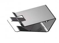
<< where I can find clamping bars for clamping chips against the heatsink? >>
I know of them as clips, and they come with the heat sink. I don't know that I personally have seen them offered separately (eBay?). They look kinda-sorta like the pic I've posted below, but there are various styles.
(the illustration is from Fourslide Stamping Product Examples: Fourslide Stampings, Miniature Parts, Clips and Wire Forms )
You can do about as well by drilling a hole, and using a screw and nut. The aluminum heat sink, and steel mounting tab, expand differently when they heat up, so use a split (spring) lock washer if at all possible.
.
Mohitkmittal, you are going to drive me to drink. Already have, in fact. I barely managed to drive home from my AA meeting, with a stop at the liquor store.
What boy or girl can find 1 thing wrong with this picture?
<< My circuit is exactly factory...Is a cap needed from Pin8...I always had just a resistor >>
Well, one quips something about kids nowadays, and tears out some more hair. Cm is a time delay capacitor for the mute. In the TI data sheet look at page 8, item 13. Yes you need it, because along with its delay function it might be doing something the data sheet doesn't explain. Data sheets are not, after all, a course in basic electronics.
Is Ci present below Ri? Its job is to hold DC gain to unity. This is extremely important (page 8, item 8).
<< where I can find clamping bars for clamping chips against the heatsink? >>
I know of them as clips, and they come with the heat sink. I don't know that I personally have seen them offered separately (eBay?). They look kinda-sorta like the pic I've posted below, but there are various styles.
(the illustration is from Fourslide Stamping Product Examples: Fourslide Stampings, Miniature Parts, Clips and Wire Forms )
You can do about as well by drilling a hole, and using a screw and nut. The aluminum heat sink, and steel mounting tab, expand differently when they heat up, so use a split (spring) lock washer if at all possible.
.
Attachments
Last edited:
Buy a strip of mild steel. 3mm to 4mm thick, 10mm to 13mm wide. Any length from 300mm to 3000mm. 15mm wide is a bit too bulky and can get in the way of other components....................Could someone please tell me where I can find clamping bars for clamping chips against the heatsink?.................
Saw off a short length that fits the width of the device + two hole diameters + 5mm
For a 3886 which is ~19.5mm wide and using M4 set screws you need a strip >=37.5mm long.
Drill the 4.1mm to 4.5mm diameter holes at 24mm centres. This should leave ~2.5mm of steel beyond each hole.
Drill and tap the heatsink @ 24mm centres.
Turn a spare nut right up to the head of the setscrew. repeat for other set screw.
Screw the set screws through the clamp into the heatsink. until they bottom or reach the clamping thickness (~6mm) whichever is first.
goop the back of the 3886. attach the mica to the 3886. goop the mica. carefully slide the 3886+mica into the clamping gap. be careful to check that the mica has not moved. or adjust to cover the backplate entirely.
screw down the clamp. Now tighten the spare nuts with a spanner till you reach the clamping force you need for the pressure specified by National.
I do this by feel because I have a lot of experience in mechanical assembly.
Last edited:
Dear @bentnsake, I am so sorry you have had to drink because of me ...but hope you save some alcohol for when we get to celebrate a nicely working amp
To your question, I do not have Cm because my mute is always off, and I never use it. Also, the amp has always been working well without the Cm, so to your point, I would say, that because electrons are not moody or act according to our wishes, why were they behaving well without it? All other components are exactly the same as the ones on the National schematic.
I do have Ci below the Ri (Ci's negative grounded), and the same value. My input passes through a 1uF 400V poly prop cap.
Also, I have completed one channel on a new board, very small layout (will post a picture soon), and the other channel is my old one. The same problem of DC offset at mid-high volume exists. I am very sure it is because of the power supply, has to be something wrong with some wire. I will tear apart the entire power supply and let you know what I find. I had recently redone the power supply, and nicely put heat shrinks everywhere. Now I have to remove all that The amp is as silent as it gets, no noise unless you put your ear next to the speaker. I have not tried grounding the positive of the input, but suspect the noise to be from the source.
I don't know why there should be DC in the output after a certain volume if it is because of a bad layout. In any case, I am also building the other channel afresh, and will keep you posted.
Also thanks Andrew for the detailed process of how to make you own clamping bars.
Thanks again, and I hope I fix this.
Best,
Mohit
...but hope you save some alcohol for when we get to celebrate a nicely working amp To your question, I do not have Cm because my mute is always off, and I never use it. Also, the amp has always been working well without the Cm, so to your point, I would say, that because electrons are not moody or act according to our wishes, why were they behaving well without it?
All other components are exactly the same as the ones on the National schematic.I do have Ci below the Ri (Ci's negative grounded), and the same value. My input passes through a 1uF 400V poly prop cap.
Also, I have completed one channel on a new board, very small layout (will post a picture soon), and the other channel is my old one. The same problem of DC offset at mid-high volume exists. I am very sure it is because of the power supply, has to be something wrong with some wire. I will tear apart the entire power supply and let you know what I find. I had recently redone the power supply, and nicely put heat shrinks everywhere. Now I have to remove all that
The amp is as silent as it gets, no noise unless you put your ear next to the speaker. I have not tried grounding the positive of the input, but suspect the noise to be from the source. I don't know why there should be DC in the output after a certain volume if it is because of a bad layout. In any case, I am also building the other channel afresh, and will keep you posted.
Also thanks Andrew for the detailed process of how to make you own clamping bars.
Thanks again, and I hope I fix this.
Best,
Mohit
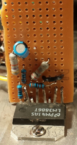
New layout
Hi guys and layout experts,
On the basis of your sound advice, I have made a new layout using my existing chip (wonder how I got so many screw driver marks on my heatsink)
It is pretty much a point to point layout, very compact, and as per the National specs for parallel (I am just using one half).
Please let me know if this looks bearable to you. The spots on the chip are from the days when I first built the amp using just point to point and hot glued between the pins to prevent shorting. You wouldnt believe I have burned 6 chips total during my early days 3-4 years ago (4 were destroyed due to a ground that broke and 2 were in paralle per channel). Other 2 probably similar cause.
Thanks,
Mohit

Hi guys and layout experts,
On the basis of your sound advice, I have made a new layout using my existing chip (wonder how I got so many screw driver marks on my heatsink
)It is pretty much a point to point layout, very compact, and as per the National specs for parallel (I am just using one half).
Please let me know if this looks bearable to you. The spots on the chip are from the days when I first built the amp using just point to point and hot glued between the pins to prevent shorting. You wouldnt believe I have burned 6 chips total during my early days 3-4 years ago (4 were destroyed due to a ground that broke and 2 were in paralle per channel). Other 2 probably similar cause.
Thanks,
Mohit
Attachments
this is the same symptom as a DC coupled amplifier has.The same problem of DC offset at mid-high volume exists.
The Power Amplifier sees the varying vol pot output resistance and the input responds by changing the output offset.
A Member cleverly discovered that orienting the chipamp to 45 degrees gets the pin pitch very close to the diagonal hole pitch.
I note you have removed the NC pins. Good.
except that the chip fixing is more flexible and you must take care not to fatigue the remaining 8pins.
I note you have removed the NC pins. Good.
except that the chip fixing is more flexible and you must take care not to fatigue the remaining 8pins.
.
<< I don't know why there should be DC in the output after a certain volume if it is because of a bad layout. >>
Just to mention this briefly, one possible cause is oscillation (feedback). DON'T zero in on this, it's uncommon, I only mention it as a for-instance.
It's possible (not likely) for oscillation to be happening all the time in the high-supersonic, and at a very low level. Even lab-grade oscilloscopes can miss it. Then x set of circumstance occurs and everything falls apart.
Don't start soldering in bypass capacitors at random points, that would be counter-productive. Because of course the engineers at the factory know all about this, and have taken steps to prevent it.
He arched an eyebrow. A half smile flickered past his lips. Did a twinkle dance in his eyes, just for a moment? "Of course," he said, "if you're not using the factory schematic, then anything can happen."
.
Thanks Andrew, I like your 45 degree tip! Also, I do not have any volume pot that might introduce DC in the circuit. My amp's volume is only controlled by the source (a laptop in my case). I am buying new barrier blocks for all my power, and let you know if that makes a difference. Right now I have those white colored round connecting things, they are fine, but I guess when there are multiple wires, a barrier block is much better because it does not damage the wires (because the contacts are flat) and also because it can accommodate wires of different thickness much better.
Another question, and not chipamp related. Because you all have advised that paralleling with a ballast may not be the best option, and even servo based amp might be unstable at times, I was thinking of putting in a tripath for my bass in the towers. My speakers are ~4 ohms, and I want to give them more juice. In the TA2022 circuit, they use 10mH 10A inductor. I can't seem to find it anywhere, any recommendations? Combination of 3886 and Tripath should be sweet I guess. I have some power to spare, my transformer is 250VA toroid, so guess should have plenty of headroom...but fixing the gainclones is first.
Thanks, I will keep everybody posted. It has been a tremendous learning experience for me because of each one of you.
Best,
Mohit
- Status
- This old topic is closed. If you want to reopen this topic, contact a moderator using the "Report Post" button.
- Home
- Amplifiers
- Chip Amps
- Gainclone DC on output