I didn't really make any direct comparisons between one and two transformers, but it seems to me that two separate add more soundstage. That's how monoblocks "feel" comparing to stereo amp.
One way to have the best of both worlds is to build two stereo amps and use them as monoblocks for biamping each channel. That's what I'm planning on doing.
One way to have the best of both worlds is to build two stereo amps and use them as monoblocks for biamping each channel. That's what I'm planning on doing.
I have been converted to die hard full ranger relatively recently, biamping, although a great idea, will not work in my case. I may at a later point in time add a pair of supertweeters to my speakers, maybe then...
Waht if I built two stereo amps and added a bridging circuit that could be switched out when needed?
Waht if I built two stereo amps and added a bridging circuit that could be switched out when needed?
More pictures.
The transformer primaries hooked up to the switch/fuse/IEC connector:
The rectifier board connected:
The audio boards mounted on the side panel. Space was tight")
Closeup of one audio board:
And finally, everything stuffed inside the enclosure. The wiring's a mess, but the hum/noise is pretty low (inaudible 3' from my 96dB speakers). I tried to keep the power supply wires to one side (left and bottom in the photo) and the audio wires on the other side (top and right).
Alright, that completes my amp and the pictures. Where are the others?
The transformer primaries hooked up to the switch/fuse/IEC connector:
An externally hosted image should be here but it was not working when we last tested it.
The rectifier board connected:
An externally hosted image should be here but it was not working when we last tested it.
The audio boards mounted on the side panel. Space was tight
An externally hosted image should be here but it was not working when we last tested it.
Closeup of one audio board:
An externally hosted image should be here but it was not working when we last tested it.
And finally, everything stuffed inside the enclosure. The wiring's a mess, but the hum/noise is pretty low (inaudible 3' from my 96dB speakers). I tried to keep the power supply wires to one side (left and bottom in the photo) and the audio wires on the other side (top and right).
An externally hosted image should be here but it was not working when we last tested it.
Alright, that completes my amp and the pictures. Where are the others?
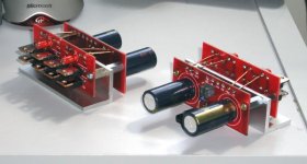
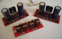
Peter Daniel said:Here's another way to create self contained modules, taking care of attaching the board and power connection. All you need is to attach transformer and inputs/outputs.
What? Are those Panasonic caps I see on Peter's boards?
 That is a pretty clever idea, though. Can you come up with something similar using two boards for a modular multi-channel/bridged amp?
Utrecht (the Neteherlands) late in supply
As I read this thread I do notice that I am not the only one in Utrecht looking foreward to the kit.
THe waiting time does bring beautifull creativity to housing designs. I have a few pages of notepad myself by now, but I do see great ideas.
Did anyone find out what type of linear (displacement) pot/system the original 47labs is using?
I wonder, my DIY experience only restarted recentley with the repair of my CD80, but back in the early eighties you could not find a good word for linear displacement pots.
It could be that they use rotary with a nylon thread or so (Like my first B&O).
On the other hand there are still a lot lin. displ pots used in studio type equipment.
Any guesses or ideas are welcome. It would broaden also my sketching options for housing.
right...
"i live in Utrecht and i got my boards today"
finished soldering parts on the board; tomorrow i'll have to fix my chassis. I'm making it fully bs-proof; all signal wiring will be teflon insulated silver and all psu wiring will be teflon insulated, silver coated, stranded copper often used in tube amps.
Viva www.ae-europe.com !
ITS ALIVE!!!! finally got everything together today and wired up. this thing is great. unfortunately put in a couple wrong resistors on a couple of the boards, but that'll be fixed in a couple minutes. however, got the first stereo pair done and listened happily for about 1/2 hr so far. thanks very much to brian for the boards and everyone else's help on everything else (figured out the transformer issue without any damage ) now just cant wait to get the case and everything drilled and mounted.
) now just cant wait to get the case and everything drilled and mounted.Attachments
I have a quick question. I am doing a 4 channel amp. In order to reduce the number of wires running around the case, can I line all of them up and put a single solid copper wire through the V+,V-,Pgnd+, and Pgnd-?
This would really make things easier. I know that I would have to run separate grounds for everyhting else though.
-Paul Hilgeman
This would really make things easier. I know that I would have to run separate grounds for everyhting else though.
-Paul Hilgeman
Illusus said:I have been converted to die hard full ranger relatively recently, biamping, although a great idea, will not work in my case. I may at a later point in time add a pair of supertweeters to my speakers, maybe then...
Waht if I built two stereo amps and added a bridging circuit that could be switched out when needed?
What if you build two stereo amps, with obtion to disconnect power to one channel on ea. amp? This way you can either have two stero amps or two real monoblocks
PHilgeman said:can I line all of them up and put a single solid copper wire through the V+,V-,Pgnd+, and Pgnd-?
This should work, but I would still rather use a star connection setup for best performance.
In case you decide to go with lining up, use thick gauge main wires (like 12ga or so) and smaller gauge jumpers through the holes.
BrianGT stereo amp alive in Oregon
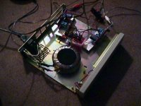
Have been enjoying Pirates of the Caribbean etc for the last few hours from a proto-setup on plexiglas, sounding nice. Will finish case in next few days and send in pics. This unit is intended for ceiling speakers in the kitchen, driven by an old headless computer in the closet (linux, turtle beach santa cruz, ads cadet am/fm radio card, network client). But anyway, the amp is sounding pretty good at the moment through Vifa studio monitors. Trafo is a center tapped shielded e-frame scavenged from old Technics, so I'm only using a single diode bridge to power +/- 38V rails.
With a good experience on this project, it will be onward and upward soon. Next up is a biamp, active crossover project. Luckily I have many more kits!
Thanks Brian for the amazing amount of effort and inspiration to help this little community. And thanks to all at diyAudio for the fun forum!
- Robert
Re: BrianGT stereo amp alive in Oregon
Sounds good. I am interested to see your finished pictures, once you finish the case.
--
Brian
RFScheer said:Have been enjoying Pirates of the Caribbean etc for the last few hours from a proto-setup on plexiglas, sounding nice. Will finish case in next few days and send in pics. This unit is intended for ceiling speakers in the kitchen, driven by an old headless computer in the closet (linux, turtle beach santa cruz, ads cadet am/fm radio card, network client). But anyway, the amp is sounding pretty good at the moment through Vifa studio monitors. Trafo is a center tapped shielded e-frame scavenged from old Technics, so I'm only using a single diode bridge to power +/- 38V rails.
With a good experience on this project, it will be onward and upward soon. Next up is a biamp, active crossover project. Luckily I have many more kits!
Thanks Brian for the amazing amount of effort and inspiration to help this little community. And thanks to all at diyAudio for the fun forum!
- Robert
Sounds good. I am interested to see your finished pictures, once you finish the case.
--
Brian
Right, I got my boards this morning, so thanks to Brian (and mere) for putting this toghether. My only problem now is that I have to wait to order an input sellector switch, and a better volume control before I can realy start putting things together in the case I have (the last one got a bit tight, so I want to make sure everything fits before I go cutting any holes in the box).
Attachments
One more question. Since I built mine in an existing chassis, I have some unused screw holes on the side panels. One of these ended up under one of the chips, and I can see the heatsink compond from the outside. Could this become a problem? I'm wondering if this will lead to 'hotspotting' (if that's the correct word), and/or the heatsink paste drying out over time due to contact with air? I'm not sure it'll cause all the paste to dry out though, because this is no different from the edge of the chip, so only the paste on the hole area might dry out. The hole is about 2mm in diameter, or even smaller.
Do you think I can leave this as it is? Do I need a new case (there's no room to mount the chip somewhere else)? I thought about putting epoxy or adhesive or something else on the outside to 'cover' the hole (at least from exposure to air), but I'm not sure if anything like that will react with the heatsink paste and just make things worse.
Any advice would be appreciated.
Thanks,
Saurav
- Status
- This old topic is closed. If you want to reopen this topic, contact a moderator using the "Report Post" button.
- Home
- Amplifiers
- Chip Amps
- Gainclone building thread based on BrianGT's boards