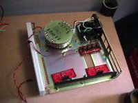
decided on doing a bit of mock up for the layout (dont have a drill or taps here at school, so no actual bolting down of sorts yet). the fan in back will be pulled out, but just felt like making sure everything fits up fine. cant believe i've been able to find heatsinks, cases, and transformers for these projects in the junk bin here at school. this is the 2-ch project box, and the 6-ch version is in the works still
Attachments
Re: Listening to it
it will be very interesting to hear comments on how it compares to the MF.
dave
net-david said:Very good sound quality.
it will be very interesting to hear comments on how it compares to the MF.
dave
Variac said:Yet another Transformer question:
I have some transformers that have just 2 wires from the secondary. Ijn other words they don't have plus minus and neutral . Just plus and minus.
Can I use one transformer of these per channel?
I think that that you need a plus, and minus and neutral ground for each channel.
I'm gonna look at the schematic but would like some backup.
Edit: Looks to me like you need AC plus, minus, and neutral from the transformer? i.e. 3 wires; even for just one channel? right?
Yes you are correct. You can use 2 transformers for both channels. One will supply the Positive rail, the other the negative.
Think of it as dual primaries, just that they aren't attached.
You can actually use a single power supply board for 2 transformers, using a single transformer for each. If it is a center tapped transformer (you can make a dual secondary transformer center-tapped also), tie the center-tap to ground (run it into one of the pgnd pads, and then put the 2 other wires into the power supply board as you would a single secondary. This will create your +V and -V voltages. Make sure that the capacitor on the power supply board is rated high enough.
If I had time, I would make a diagram.
This should be an easy way to use the cheap PE transformers.
(in other words, one bridge per channel, instead of the dual bridge topology)
--
Brian
If I had time, I would make a diagram.
This should be an easy way to use the cheap PE transformers.
(in other words, one bridge per channel, instead of the dual bridge topology)
--
Brian
MF = Musical Fidelity
The rest of the system in my "office":
Musical Fidelity A3 24 DAC
Musical Fidelity A308 integrated amp
REL Stadium III sub
I've got the LM3875 back on, listening to more Floyd while I build a PC for my inlaws. I need to come up with a switching system to A/B the amps. Maybe a couple of DPDT relays and a wall wort power supply.
I also have a Roksan Kandy KA-1 MkIII amp to compare the LM3875 to. And Monitor Audio Silver S1 to use instead of the B&W 805s.
But, alas, our new baby keeps me from doing any intense listening tests. Perhaps next weekend my wife and daughter will go shopping and I can spend some time. Hopefully I will have real transformers and an Alps Black Beauty by then.
David
matjans said:dave: MF ?
The rest of the system in my "office":
Musical Fidelity A3 24 DAC
Musical Fidelity A308 integrated amp
REL Stadium III sub
I've got the LM3875 back on, listening to more Floyd while I build a PC for my inlaws. I need to come up with a switching system to A/B the amps. Maybe a couple of DPDT relays and a wall wort power supply.
I also have a Roksan Kandy KA-1 MkIII amp to compare the LM3875 to. And Monitor Audio Silver S1 to use instead of the B&W 805s.
But, alas, our new baby keeps me from doing any intense listening tests. Perhaps next weekend my wife and daughter will go shopping and I can spend some time. Hopefully I will have real transformers and an Alps Black Beauty by then.
David
Ped,
That was what I was planning to do, but using 2 DPDT relays (or one 4PDT) to switch all 4 wires for 2 channels. I don't feel comfortable tying the - terminals of different amps together. If one was bridged and the other used common ground for the speaker -, there would be some smoke loss")
David
That was what I was planning to do, but using 2 DPDT relays (or one 4PDT) to switch all 4 wires for 2 channels. I don't feel comfortable tying the - terminals of different amps together. If one was bridged and the other used common ground for the speaker -, there would be some smoke loss
David
(repost from main thread)
I put up my users guide on my new domain, BrianGT.com. I haven't created a website yet, as I have been beyond busy with other things.
http://www.BrianGT.com
Larger, high resolution pictures from the manual can be found here:
http://brian.darg.net/gallery/nigc-kit
I will be adding a bunch of material to the manual, and had intended for it to be more complete before posting it, but since the kits are already out there, I decided to post the incomplete manual.
--
Brian
Coulomb said:Got my boards today Brian, they are so Dainty..
Anthony
heh.. dainty. I guess that is one way to put it.
When are you going to finish your cd player?
--
Brian
Got the transformers today, I have enough parts to build the FRED rectifiers, I am just waiting on the Super regulators.
I suppose I could get it running on bench supplies and my AD317 regulators, but I have stopped working on it for a while. I was spending way to much time on it, had to take a break.
Anthony
I suppose I could get it running on bench supplies and my AD317 regulators, but I have stopped working on it for a while. I was spending way to much time on it, had to take a break.
Anthony
PHR said:Just a question, since this amp is a NI this means that the out signal is inverted in(+) out(-)?
Thanks
PHR
No. NIGC = Non-Inverted GainClone. IGC = Inverted GainClone.
More questions while I wait for my kit to arrive:
* Does the chip come with the legs bent like that, or do I have to bend the legs to line up with the PCB holes? I hope it's the former
* Are the PCB dimensions posted anywhere? I'm a little worried I might have picked too small of an enclosure.
* Is it a *really* bad idea to mount the chip to the heatsink/enclosure and leave the PCB hanging? I already have holes in my enclosure (I'm using some old instrument case) that I'd like to use, which means I can't get PCB standoffs to work. I could glue little wood pieces under the PCB to support them (or something else along those lines), or I'll have to drill new holes in the enclosure.
Thanks in advance. I took some pictures of my enclosure (transformer in place, RCA connectors and binding posts added), I'll post them in a little while.
Saurav
Yes, the legs are already bent and match the holes on the PCB.Saurav said:More questions while I wait for my kit to arrive:
* Does the chip come with the legs bent like that, or do I have to bend the legs to line up with the PCB holes? I hope it's the former
Each board (inluding PS board) is 1 3/16 x 2 7/8 inches, about 3.02 x 7.3cm.
* Are the PCB dimensions posted anywhere? I'm a little worried I might have picked too small of an enclosure.
* Is it a *really* bad idea to mount the chip to the heatsink/enclosure and leave the PCB hanging? I already have holes in my enclosure (I'm using some old instrument case) that I'd like to use, which means I can't get PCB standoffs to work. I could glue little wood pieces under the PCB to support them (or something else along those lines), or I'll have to drill new holes in the enclosure.
I wouldn't recommend it. The boards and caps don't weigh all that much, but over time, especially with the chip heating up and cooling down frequently, it could cause the chip's mounting tab to bend or break. Wood or plastic supports would work fine, and I'm sure you could find standoffs of the right size somewhere, anyway.
- Status
- This old topic is closed. If you want to reopen this topic, contact a moderator using the "Report Post" button.
- Home
- Amplifiers
- Chip Amps
- Gainclone building thread based on BrianGT's boards