This transistors circuit limits the voltage the output integrator at level 0,55V for each half-wave. Adjustment can be carried the right choice between the coefficient the gain section UcD and integrator. The difference should be about 5-8%.
These thus introduced a DC offset in the output integrator section that reaches to 0,5-0,6V at high modulation index. Limmiter circuit is slightly opened, thereby reducing the gain of the integrator or complitely turn it off .
Instead of transistors can be used dual diodes, but it will give the worst result due to voltage-current characteristics of the diodes used. Already at approximately 0,3-0,4V forward volt. leakage through such 1n4148 is unacceptable and, moreover, the non-linear, which makes the addition of the integrator in the scheme meaningless.
Perhaps the best result will be in the microwave mixer diodes ???
I'm sorry, poor knowledge of the language makes it impossible to explain more clearly
Last edited:
This transistors circuit limits the voltage the output integrator at level 0,55V for each half-wave. Adjustment can be carried the right choice between the coefficient the gain section UcD and integrator. The difference should be about 5-8%.
These thus introduced a DC offset in the output integrator section that reaches to 0,5-0,6V at high modulation index. Limmiter circuit is slightly opened, thereby reducing the gain of the integrator or complitely turn it off .
Instead of transistors can be used dual diodes, but it will give the worst result due to voltage-current characteristics of the diodes used. Already at approximately 0,3-0,4V forward volt. leakage through such 1n4148 is unacceptable and, moreover, the non-linear, which makes the addition of the integrator in the scheme meaningless.
Perhaps the best result will be in the microwave mixer diodes ???
I'm sorry, poor knowledge of the language makes it impossible to explain more clearly
Hmm first of all (and I have to see in spice also), how would circuit behave without limiter? Does it mean that THD rises with modulation index, when integrator limiter turns on ?
I wonder what is the cause, why we need integrator limiter at high modulation index at all ? Maybe it cam be done without the limiter?
Without the limiter amplifier can go on to the generation of low frequency of about 50-80 kHz with an amplitude of power magnitude. This is clearly seen in the simulation.
Until the inclusion limiter on THD does not affect.
In addition, the failure of the generation frequency can occur in the presence of a high slew rate audio signal, or high frequency signal.
Read the ncore white paper on hypex website.
Until the inclusion limiter on THD does not affect.
In addition, the failure of the generation frequency can occur in the presence of a high slew rate audio signal, or high frequency signal.
Read the ncore white paper on hypex website.
Last edited:
Without the limiter amplifier can go on to the generation of low frequency of about 50-80 kHz with an amplitude of power magnitude. This is clearly seen in the simulation.
Until the inclusion limiter on THD does not affect.
In addition, the failure of the generation frequency can occur in the presence of a high slew rate audio signal, or high frequency signal.
Read the ncore white paper on hypex website.
I can not find that paper on their web page, can you link or upload ?
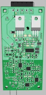
A new version of the amplifier with improved parameters and more convenient to install.
hi sous nice layout .please share your schematics and photos of your project
Stewin: You can find the basic schematic at beginning of thread. This is good to deserve some work, don't expect it at zero work.
Good work: Differential amplifier, differential modulator, duty clamp. The modulator can be redesigned for lower part count and lower cost parts, but for hi-end the implementation is right.
The duty clamp can be elaborated more: a TL074 to get a (low cost) reference from total supply voltage, calculate base drive voltage with a diode for temperature compensation, and feed symmetrically the BJTs. The idea came when solving the problem for a 4ch amplifier, requiring more carrier amplitude at comparator input than allowed by the b-e voltages of BJT when hot (~400mV @ 100C), thus requiring 4 resistors for each channel to make a divider for each clamp transistor base, then the centralized solution idea came, since it uses same or less amount of parts and is more accurate. It can feed the bases or the emitters, each option has its own complexity. There is also the shortcut of wiring the collectors directly to the integrator input, but it has its own complexity too, some restrictions on operating conditions.
This is just the simplest version. Since the network already has a service manual for "nc 400" you can see the circuitry there.
The fully differential modulator worked well, but the implementation of the PCB made the assembly very laborious.
I simplified new device as much as possible.
The fully differential modulator worked well, but the implementation of the PCB made the assembly very laborious.
I simplified new device as much as possible.
Last edited:
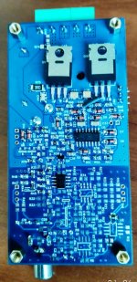
First prototype
Very neat design, thanks for sharing!
and, how is the output power for 8ohm load?
AgreeThank you very much Erica!
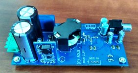
Power is limited by output transistors.

Service step-down stabilizers can operate up to +/- 90V.
I think 200W at 8Ohm should be for IRFB5615
For IRFB4227 it will be necessary to increase dead time, I did not try.
Yes, i want to know the working range of the dc-dc convert to support the gate driver circuit,
Also, i had try to build the amp with the IRS20957 plus IRFB4227, the dead time setting to 25ns, with the regualted power supply(daul 90V) to get 450W output for the 8ohm load! This IRFB4227 is very good MOSFET.
You have 1 comparator with 1 output signal that is duplicated later. You can call it differential, but it doesn't have any benefit over the basic circuit. Contrary to your design it is possible to use 2 different modulators that carries different informations and can be used to suppress unwanted modulation artifacts. That would be fully differential in my terminology.
You mean 3 level PWM ?
So workhorse still alive
My discrete UcD has fully differential.
Check my thread.
Well that is 2 level PWM we usually call it AD mode. The 3 level PWM which is BD mode is in true sense fully differential IMHO.
Though, one can call the 2 level PWM AD mode as balanced input and bridged output for sure
Last edited:
Well that is 2 level PWM we usually call it AD mode. The 3 level PWM which is BD mode is in true sense fully differential IMHO.
Though, one can call the 2 level PWM AD mode as balanced input and bridged output for sure
You are right.
Do you have any topology description for reference for class BD?
I am thinking to make it.
- Status
- This old topic is closed. If you want to reopen this topic, contact a moderator using the "Report Post" button.
- Home
- Amplifiers
- Class D
- full differential UcD modulator with extra integrator