How is it going? You may have the results?In differential mode the modulator ensures very low DC. In common mode the voltage will be exactly half way between power rails, and there is no way to change it.
I'm working on a really differential self-oscillating amp, but in that you can set common mode voltage independently (however the optimal value is almost in the middle).
Or your design project is still top secret?
I have results, but I'm not satisfied with it yet. I only achieved -102 dB SNR because of a small interference on the breadboard prototype. It should be around -110 dB with only gaussian noise, but the basic concept works exactly as intended. It is not on PCB yet, but the 4 layer PCB design (6 channels of 80 W or more full bridge on 100*100 mm) is very close to finish. I hope with a correctly designed PCB will not have the interference.
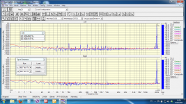
These are the signals observed on scope (red: differential output voltage):
Small signal:

Small signal and carrier:

Large signal:

Large signal triangle:

Small signal transient response:

Large signal transient response:

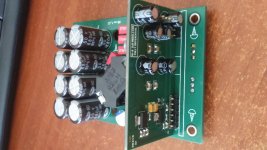
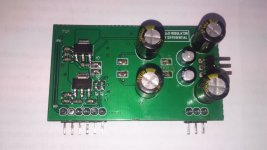
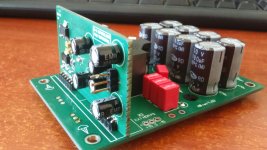
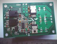
View of PCB:

These are the signals observed on scope (red: differential output voltage):
Small signal:
Small signal and carrier:
Large signal:
Large signal triangle:
Small signal transient response:
Large signal transient response:
View of PCB:
Last edited:
my friend has implemented a similar scheme without servo, products launched in the series. full bridge TAS5162 and similar type MDR
Your statement about the need for servo easily check in the simulator.
Of course, the experiment will show who was right. However, the simulator is not deceived me
Well, if you can not find the similarity, what can I do?
I wrote "In differential mode the modulator ensures very low DC." Do you disagree?
About similarity:
You showed schematic, Bruno didn't. You didn't show stability analysys, Bruno did. What to compare? I don't have the service manual of NAD m22.
Unfortunately attachments removed
IMD test 35Vp-p
I still can see the attachments.
Very nice result! As soon as I can get rid of interference I'm going to measure distortion figures also.


An interesting project, Pafi.
A modulator, as I understand it, the digital?
It would be interesting to see 6k distortion on the actual load.
And the carrier frequency at the output to 10W of power without the use of an oscilloscope filter.)))
(We conducted experiments on vegalab: measurements on the loudspeaker (not the resistor) show very poor results for digital modulators without feedback. I had the idea to add an additional integr. on digital modulator input for the add feedback, but so far it's only distant plans.)
If the modulator is analog, it is interesting how you solved the problem with a reduced carrier frequency at high modulation index. As far as I know, the integrated output stages are very sensitive to lower frequencies below 150 kHz.
Thanks, Bimbla.
A new version of the inverter slightly improved results, in addition I have used step down converter LM5008 for the IRS20957 power supply
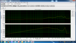
10W
3.3 Ohm resistive load
THD&N vs freq
AMP-bottom graph
A new version of the inverter slightly improved results, in addition I have used step down converter LM5008 for the IRS20957 power supply
10W
3.3 Ohm resistive load
THD&N vs freq
AMP-bottom graph
Attachments
Last edited:
I must say that, nevertheless, failed to get the values that are achieved in the original ncore.
The circuit layout is very critical to the power section of the inverter. It is advisable to do a 4-layer board. And the dynamic dead time control is desirable
However, it turns out a good amp for home use, THD + noise 1-15 watts less than 0.0015%
Sous:
Why would it matter at all ? Whats the point of having 0,0001 thd vs 0,001 thd ? Humans can not hear the difference:
BUT, you used sound card, they used Audio Precision, with AES17 low pass filter designed just for class D testing .. So they easily achieve one zero after decimal point more, but whats the purpose?
Pafi:
Can you explain fully differential amplifier regarding UCD? : What about two half bridge amplifier in bridge mode , hmm ?
Last edited:
Oh, it's a sports interestSous:
Why would it matter at all ? Whats the point of having 0,0001 thd vs 0,001 thd ? Humans can not hear the difference:
BUT, you used sound card, they used Audio Precision, with AES17 low pass filter designed just for class D testing .. So they easily achieve one zero after decimal point more, but whats the purpose?

hi sous .i have many ir2110 from my previous projects can i use ir2110 instead of irs2092 with your modulator???
These ICs are not very suitable. Input PWM inverter should be added to 2110, solve the problem of cross-currents (no dead time). And spread over time will give the worst result for the distortion. 2092 is not suitable for use in UcD mode.
These ICs are not very suitable. 2092 is not suitable for use in UcD mode.
here in the below forums it is used successfully http://www.diyaudio.com/forums/class-d/255046-systemd-liteamp.html
http://www.diyaudio.com/forums/class-d/255046-systemd-liteamp-58.html
http://www.diyaudio.com/forums/class-d/255046-systemd-liteamp-60.html
http://www.diyaudio.com/forums/class-d/166214-ucd-25-watts-1200-watts-using-2-mosfets.html
http://www.diyaudio.com/forums/class-d/166214-ucd-25-watts-1200-watts-using-2-mosfets-356.html
http://www.diyaudio.com/forums/class-d/166214-ucd-25-watts-1200-watts-using-2-mosfets-456.html
Hi! sure you can, but it makes no sense. Industrial driver in 2110 on all parameters worse than the audio driver 20957. As a result 2110 in UcD mode will be 0.07% distortion. And it is in the best case. While 20957 give a 0.009% does not require extra IC body,includes protection circuitry elements, and the dead time generator. In addition, you will have problems with the configuration of the output stage for 2110. Maybe just exceeded the level of EMI...
Last edited:
- Status
- This old topic is closed. If you want to reopen this topic, contact a moderator using the "Report Post" button.
- Home
- Amplifiers
- Class D
- full differential UcD modulator with extra integrator