No hum and fantastic sound. I will order some more. I do not like starground but bus.
Great.

I'll order more too, but I am waiting for the Monolith since I imagine it will have the holes pre-done on the heatsink; my limiting step.
Cheers,
M.
No hum and fantastic sound. I will order some more. I do not like starground but bus.

... waiting for the 240 w version.
For all waiting to the First One L - 250 W/8 Ohm module, here's preliminary PCB drill plan to enable you to prepare your heatsinks and chassis in advance.
Overall height of the assembled module is 42 mm.
")
Attachments
Monolith & Black Mamba chassis & FO L module .. prices & delivery terms all set & published next week
Great.
We would like to know also if Monolith will be offered as pictured before (only heatsink and support for the connectors) which is ideal for active speakers, or as a complete box.
Regards,
M.
Cool! Do you have a website or similar where you could publish all information and docs together at one place? Spreading this all over this thread is getting messy...Monolith & Black Mamba chassis & FO L module .. prices & delivery terms all set & published next week
Thanks, L.C.
Hi Guys,
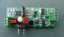
I m sharing with you the outcome of a small project for FO which is a small PCB for providing a differential input for the FO and also to facilitate bridging or use with single smps.
The PCB is 51 x 21mm and contains 2 discrete regs (+/-12) and 1 or 2 That 1200.
it is made to be soldered close to the FO and can be powered by the hypex +/-21V Aux.
The benefit of using a That is obviously to provide differential input capabilities, but also to enable integration of 2 FO with a single SMPS by uncoupling the 0V Signal thus ensuring expected damping and very high crosstalk.
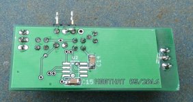
A second That can be soldered on the botom side, in order to just invert the same input and then to drive a second FO to "bridge zem all".
I have not done any listening in bridge config, but I can tell you the FFT is wonderfull, most of the residual 100hz harmonic from smps are gone. Br
I have 5 pairs of PCB left for whomever want to play with this and share with us. anyone interrested please send PM and I might open a thread for further talk. Pinnochio please send me your adress by PM
I m sharing with you the outcome of a small project for FO which is a small PCB for providing a differential input for the FO and also to facilitate bridging or use with single smps.
The PCB is 51 x 21mm and contains 2 discrete regs (+/-12) and 1 or 2 That 1200.
it is made to be soldered close to the FO and can be powered by the hypex +/-21V Aux.
The benefit of using a That is obviously to provide differential input capabilities, but also to enable integration of 2 FO with a single SMPS by uncoupling the 0V Signal thus ensuring expected damping and very high crosstalk.
A second That can be soldered on the botom side, in order to just invert the same input and then to drive a second FO to "bridge zem all".
I have not done any listening in bridge config, but I can tell you the FFT is wonderfull, most of the residual 100hz harmonic from smps are gone. Br
I have 5 pairs of PCB left for whomever want to play with this and share with us. anyone interrested please send PM and I might open a thread for further talk. Pinnochio please send me your adress by PM
Attachments
Well, 1 hour listening session with 2 PCB as differential input (no more bridge), very good separation of the chanel which immediately brings a scene of instruments instead of music in the center. Also inverting one chanel input (very easy by swaping In+ and In-) and reverting the loudspeaker wiring gave an ultimate Bass experience ! because usually the bass are spread equally on both chanel and then by inverting one chanel, you equally pump on both rail and then get about twice the Joule capacity of each cap. this single hypex is very great in this condition
Plug your FO, find a good flac or wav for this song and you ll get stuck:
https://www.youtube.com/watch?v=MOVuGQTuTBc
LC, please put your hands on the bench and design us a Differential FO version 1.5 !
!
Plug your FO, find a good flac or wav for this song and you ll get stuck:
https://www.youtube.com/watch?v=MOVuGQTuTBc
LC, please put your hands on the bench and design us a Differential FO version 1.5
!
Last edited:
Almost there guys...
I am getting close, I only have my input signal and speaker wires to fabricate and hook up.
Power supplies work as expected and the First Ones leds light up.
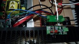
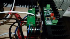
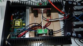
I only have one DMM, so adjustments are slow and tricky. I am glad this is a trial all You expert amp builders go thru also. I started out doing something noob-ish, I laid the heatsinks down, for easier measuring, but found of course this did not allow proper heat dissipation. So I attached the heatsinks to only one side of the chassis bottom plate and fabricated some wood blocks to keep everything level (See photo below). Many of You can easily test this with a fully enclosed chassis, but for me, with far sighted vision and blind in one eye to boot, I need to make this as open as possible. (there are times I miss the near-sighted vision I had before getting cataract and having a lens implant)  Once I have everything dialed in closer, and the amp has 100 hours into it, I will re-calibrate, with a fully assembled chassis.
Getting DC offset close to zero was not a problem. But getting the VAS idle bias (TP1-TP2 or TP3-TP4) down to 180 mV AND getting the DC offset to zero did not seem possible. The VAS idle bias started out at 560 mV And that was after an hour of warm-up time. The closest I got was 350 mV, but it was getting late, and I do not think I was giving the module enough time to stabilize. So I decided I would stop and come back to it this weekend.
The bummer for me, is the long, long, long work week a have. Monday thru Friday is ALL work no play, so I live for my play on the weekends. I keep saying, "this will be the weekend I get the First One done"... ...well it has been five weekends already! 
I am feeling pretty confident about this weekend, and I am sure the blood sweat and tears expended can only make the reward that much sweeter.
And, I have not forgotten about posting photos. They are coming. The plan is, to be enjoying my First One amp as I post them, and also posting them in order so other builders will have a guide, all in one part of this thread instead of scattered all over.
Hope to be posting back soon with impressions
Allen
I find it impossible to adjust DC. One channel 35 mv and the other 51
Yet it is well explained on the instructions paper...
First, patience. Next, let warm the amp for one hour.
Then write a column on a paper of the effect on bias and DC offset of each move of each trimmer.
Then trim with patience, given the above, and when you arrive at a promising level, let stabilize again and return measuring after half an hour or so.
With the approach above, I got 7mV on one channel and I thought something was wrong on the other because I got 0mV.
Good luck,
M.
Until you wake us up
Guess its nearly same process as with VSSA amp and maxlorenz can maybe confirm that, it was nearly impossible go in 0-5mV area without having two DMM connected at same time as suggested in manual, also i made below visual for VSSA amp to help understanding under calibration.
I am getting close, I only have my input signal and speaker wires to fabricate and hook up.
Power supplies work as expected and the First Ones leds light up.
I only have one DMM, so adjustments are slow and tricky. I am glad this is a trial all You expert amp builders go thru also.
I started out doing something noob-ish, I laid the heatsinks down, for easier measuring, but found of course this did not allow proper heat dissipation. So I attached the heatsinks to only one side of the chassis bottom plate and fabricated some wood blocks to keep everything level (See photo below). Many of You can easily test this with a fully enclosed chassis, but for me, with far sighted vision and blind in one eye to boot, I need to make this as open as possible. (there are times I miss the near-sighted vision I had before getting cataract and having a lens implant) Once I have everything dialed in closer, and the amp has 100 hours into it, I will re-calibrate, with a fully assembled chassis. Getting DC offset close to zero was not a problem. But getting the VAS idle bias (TP1-TP2 or TP3-TP4) down to 180 mV AND getting the DC offset to zero did not seem possible. The VAS idle bias started out at 560 mV
And that was after an hour of warm-up time. The closest I got was 350 mV, but it was getting late, and I do not think I was giving the module enough time to stabilize. So I decided I would stop and come back to it this weekend. The bummer for me, is the long, long, long work week a have. Monday thru Friday is ALL work no play, so I live for my play on the weekends. I keep saying, "this will be the weekend I get the First One done
"... ...well it has been five weekends already! I am feeling pretty confident about this weekend, and I am sure the blood sweat and tears expended can only make the reward that much sweeter.
And, I have not forgotten about posting photos. They are coming. The plan is, to be enjoying my First One amp as I post them, and also posting them in order so other builders will have a guide, all in one part of this thread instead of scattered all over.
Hope to be posting back soon with impressions
Allen
Attachments
Good Saturday morning!
I am going for "optimal working conditions" as stated in the manual:
* VAS idle bias current (18 mA) - measured as 180 mV between TP1-TP2 or TP3-TP4
* output DC offset voltage (0 mV)
* supply idle bias current (280 mA)
Have You other First One builders found a way to read TP1-TP2 or TP3-TP4 without having to constantly "probe" and hold the probes in place? I am thinking I could solder a small lead wire in place and clip onto that, so then I can just turn screws. I plan on tapping off my speaker wires for the DC offset.
Actually, I am heading to my local electronics store to see what they have. My current DMM seems to give pretty accurate Volt and Resistant readings, but the current readings have always been "off". The range seems out of wack for some reason - the numbers are right, but the decimal place is not and does not change when adjusting the decimal place or range. So I am thinking a second unit would be nice to cross-reference...
What bias are you targeting at?
I am going for "optimal working conditions" as stated in the manual:
* VAS idle bias current (18 mA) - measured as 180 mV between TP1-TP2 or TP3-TP4
* output DC offset voltage (0 mV)
* supply idle bias current (280 mA)
Have You other First One builders found a way to read TP1-TP2 or TP3-TP4 without having to constantly "probe" and hold the probes in place? I am thinking I could solder a small lead wire in place and clip onto that, so then I can just turn screws. I plan on tapping off my speaker wires for the DC offset.
Given your investment of time and effort (and passion), maybe just get another DMM (assuming that will make life easier for you)?
Actually, I am heading to my local electronics store to see what they have.
My current DMM seems to give pretty accurate Volt and Resistant readings, but the current readings have always been "off". The range seems out of wack for some reason - the numbers are right, but the decimal place is not and does not change when adjusting the decimal place or range. So I am thinking a second unit would be nice to cross-reference...The good and the bad
First the not so hard to over-come bad:
These Molex pins on the input wires are kicking my %$$!
6 broke... (4 while inserting them into the casing)
2 lost in my studio somewhere...
2 left...
Molex a no go for me, too small and delicate, will not be buying more. I am sure there is a special tool for these finicky things, but I will not be getting it for four connections.
I really wanted to keep everything modular, in case I wanted to try the silver wire thing down the road, but my OCD will suffer this one with direct soldered connectors to the input pins to the amp modules. Easy enough to un-solder and re-solder.
Now the Good:
Left module is:
VAS idle bias is 186 mV
DC offset between .7 and 0 mV
Supply idle bias is 281 mA
Right module is:
VAS idle bias is 184 mV
DC offset between 0 and -.5 mV
Supply idle bias is 281 mA
Second DMM helped. It also helped me figure out the range issue with the other DMM: My older DMM would not allow the full voltage thru the mA setting, I needed to set it to A and use the higher current jack. Unfortunately, that unit could only read two decimal places back, so I could get 28_. The newer DMM, had more decimal places so I could dial in that last digit.
So I am ready to finish assembling the chassis and installing the signal wiring without the Molex connector...
At some week here, this kit will be playing some music!
At some week here, this kit will be playing some music!
All effort involved certainly will be greatly rewarded. The better the source the better the sound, nothing new said, as lately I fell on to Analog DAC.

All effort involved certainly will be greatly rewarded. The better the source the better the sound, nothing new said, as lately I fell on to Analog DAC.
Please share.
- Home
- Vendor's Bazaar
- First One - mosFET amplifier module