I you liked the "Bill Whitlock of Jensen Transformers Seminar" paper, you may also like:
The Jim Brown of Audio Systems Group white paper:
"Power and Grounding for Audio and Audio/Video Systems"
http://www.audiosystemsgroup.com/SurgeXPowerGround.pdf
"The TRUTH" from ExactPower of Middle Atlantic Products
http://www.exactpower.com/elite/wpapers.aspx
or a long version of the same paper
"Power White Paper" from Middle Atlantic.com
http://www.middleatlantic.com/power.htm
You may not need/want that much power (P03A bridged). I had a pair of LM4780 bridged giving approximately 115W per channel to my floor standing 3-ways. Recently built a pair of LM3886 giving "only" 30W per channel with the same power supply and approximately the same gain. It sounds louder if anything. Measured with my scope I'm using only about 2W at higher than normal listening volume. With an average speaker sensitivity of 89dB/W, 30W will get you 104dB. Of course if I up the voltage I could get 50W, and at 30W the distortion will be much less.
I suspect you'll have to sort out the finishing yourself although anodizers aren't hard to find.
I'd be interested to know what they quote you for the work. I'm considering using them in the future.
Unbelievably expensive... Got other quotes too, much cheaper, but not as cheap as I would want them. Obviously money grows on trees in the UK.
I am likely to be using PCB boards as "panels". One suggestion is to get them silver plated and then print on them followed by sealing with clear varnish. Another suggestion is to have them painted with black solder mask. The supplier has not replied to me yet. But he did make for me some beautioful boards at a good price. A whole stack of them!
Haven't posted for quite a while, but I haven't been idle. The momentary pushbutton circuits are complete as are the soft start circuits. I'll post some picturse shortly. I do have a couple of issues arising and I'll capture these when I post the pictures.
I've also built a SSMH headphone amp based on a kit by beezar. It was really nice to just order the kit, build it, test it and listen to it.....with the build taking a couple of evenings. Cheaper too!
I've also built a SSMH headphone amp based on a kit by beezar. It was really nice to just order the kit, build it, test it and listen to it.....with the build taking a couple of evenings. Cheaper too!
I have built the ε24 and σ24, so here are a few pictures.....
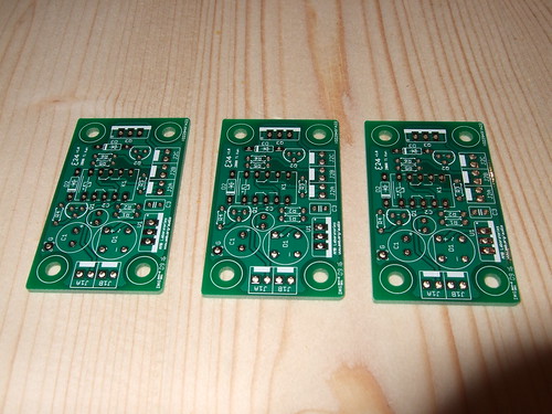
ε24 PCBs
I've got three of these boards; one for each power amp and one for the pre-amp. Not sure which pre-amp I'll build yet. Something with valves might be nice.
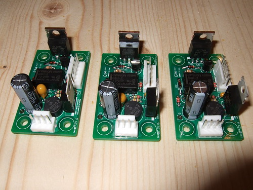
ε24 PCBs populated with components.
The ε24s were easy to build and no issues were encountered along the way. That said, I haven't actually tested them yet.
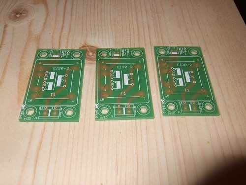
σ24 PCBS.
Here are the corresponding three σ24 PCBs....one per ε24.
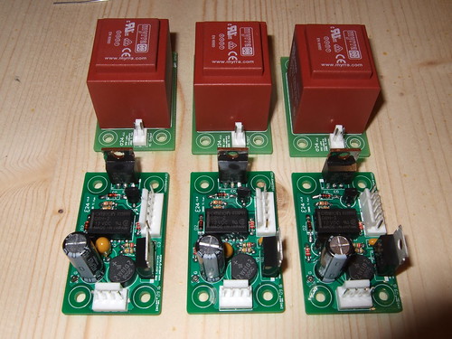
ε24 and σ24 PCBs populated with components.
Again, no issues with construction to report.
The transformer provides 12VAC which, after rectification, should provide about 17VDC. A regulator is used to drop this down to the required 12 VDC. A stable voltage, as provided by the regulator, is required to prevent false triggering of the circuitry because fluctuations in voltage can fool the circuit into thinking the pushbutton switch has been pressed.
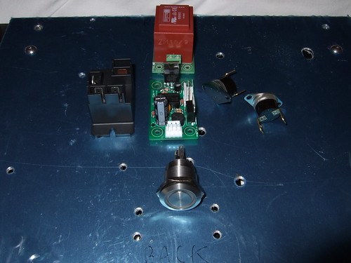
Power switch components for one amp.
So, in the centre is the ε24 with the σ24 directly behind it. To the left of the ε24 is the relay which switchs the main power supply to the soft start circuit. To the right are the thermal sensors. At the front is the push button switch.
The thermal sensors, which I'll attach to the chips, when triggered cause an onboard relay to act to simulate a button press, thereby turning off the amp. At this point the switch (which has dual LEDs) will show a red LED, indicating a fault condition. When the temperature drops sufficiently, the sensors will open causing the relay to simiulate the button being pressed again, thereby turning on the amp. The red LED on the switch will be replaced by a blue LED.
Oh, and the ε24 is designed to sit on top of the σ24, making for a much more compact component.
All in all, sweet!
ε24 PCBs
I've got three of these boards; one for each power amp and one for the pre-amp. Not sure which pre-amp I'll build yet. Something with valves might be nice.
ε24 PCBs populated with components.
The ε24s were easy to build and no issues were encountered along the way. That said, I haven't actually tested them yet.
σ24 PCBS.
Here are the corresponding three σ24 PCBs....one per ε24.
ε24 and σ24 PCBs populated with components.
Again, no issues with construction to report.
The transformer provides 12VAC which, after rectification, should provide about 17VDC. A regulator is used to drop this down to the required 12 VDC. A stable voltage, as provided by the regulator, is required to prevent false triggering of the circuitry because fluctuations in voltage can fool the circuit into thinking the pushbutton switch has been pressed.
Power switch components for one amp.
So, in the centre is the ε24 with the σ24 directly behind it. To the left of the ε24 is the relay which switchs the main power supply to the soft start circuit. To the right are the thermal sensors. At the front is the push button switch.
The thermal sensors, which I'll attach to the chips, when triggered cause an onboard relay to act to simulate a button press, thereby turning off the amp. At this point the switch (which has dual LEDs) will show a red LED, indicating a fault condition. When the temperature drops sufficiently, the sensors will open causing the relay to simiulate the button being pressed again, thereby turning on the amp. The red LED on the switch will be replaced by a blue LED.
Oh, and the ε24 is designed to sit on top of the σ24, making for a much more compact component.
All in all, sweet!
Last edited:
I have also used one of those encapsulated transformers for my soft-start (which works beautifully by the way) and it gets very hot, I'd say 60 C, with no load on it, it just gets hot by itself.
To make sure, I just plugged a spare one to the mains, with nothing connected to it, left it for 10 minutes, same thing.
I will ring the makers today if I remember to enquire about this. How hot do yours run?
To make sure, I just plugged a spare one to the mains, with nothing connected to it, left it for 10 minutes, same thing.
I will ring the makers today if I remember to enquire about this. How hot do yours run?
Akis, I've got a laminated core transformer like that, we estimated it at 15-17VA, 18V. It gets hot as well, very slowly, no matter what the load on it is. I was wondering the same thing but it's been 1/2 a year now and it doesn't seem to be troubled at all by this. It's powering my headphone amp, which is running almost all the time ")
Oh, and there is a very good line filter before the transformer. Apparently it makes no difference.
Oh, and there is a very good line filter before the transformer. Apparently it makes no difference.
I have also used one of those encapsulated transformers for my soft-start (which works beautifully by the way) and it gets very hot, I'd say 60 C, with no load on it, it just gets hot by itself.
To make sure, I just plugged a spare one to the mains, with nothing connected to it, left it for 10 minutes, same thing.
I will ring the makers today if I remember to enquire about this. How hot do yours run?
Well, the transformer above is a dedicating to the switch circuit. I have another 9VAC toriodal transformer for the soft start! So, there's three transformers in total per amp.
I don't know how hot the transformer runs yet cos I haven't tested any of the circuits. I'm gonna build them all first and then start the integration and testing of the modules. But I will post my findings.
Here's a picture of the P39 soft start circuits (one per power amp).
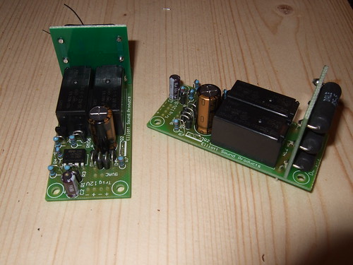
A couple of observations.......
The bank of resistors (on the vertical PCB) cause the two of mounting holes to be partly obscured....meaning that it's not going to be as easy as I would liked it to be to mount the board.
The order of construction specified by Rod is just wrong. I realised this just in time and changed the order myself. Might be simply down to the parts I bought but I don't think so.
The method of connection for the 240 VAC is simply soldering the wires to the PCB. I prefer something more mechanical myself and want to fit something like a terminal block. Unfortunately, because the PCB is single sided, I need to put it on top and the damn resistors are in the way. So, I think I'm going to have to separate the boards and try and mount the resistor board above and parallel to the main PCB or keep it vertical but raise it up enough to get the terminal block onto the PCB. This is just a hassle!
And finally, a small point - I just don't like vertically mounted resistors and diodes. I would have prefered a bigger board.
Indentally, I think I may have messed up on the resistors and would be grateful if someone could confirm that the ones I have are alright. The BoM specifies 5W power resistors. I got the wire wound resistors you can see in the picture. However, I have subsequently seen a picture of Rod's implementation (and others) and they seem to have gone for the ones which are clad in an inorganic potting compound. Should I have gone for these? What does the inorganic potting compound do?
Power resistors come in a myriad of shapes and sizes. I remember using 10W cement resistors about 10 years ago in my first DIY project, those were some really weird ones.
In the end of the day what you care about is only the power rating and sometimes the inductance. The rest of the difference is in modes of failure and failure is something you make sure won't happen.
In the end of the day what you care about is only the power rating and sometimes the inductance. The rest of the difference is in modes of failure and failure is something you make sure won't happen.
Akis, I've got a laminated core transformer like that, we estimated it at 15-17VA, 18V. It gets hot as well, very slowly, no matter what the load on it is. I was wondering the same thing but it's been 1/2 a year now and it doesn't seem to be troubled at all by this. It's powering my headphone amp, which is running almost all the time
Oh, and there is a very good line filter before the transformer. Apparently it makes no difference.
I was told by Farnell that these are encapsulated, and they trap the heat in, and as a result reach 70 C easily.
My "mistake" was that I placed it too close to a relay (4mm) and now the relay gets warm unnecessarily.
I've been doing a little testing this evening. Interestingly, it was more of an experiment to support some statements I had made elsewhere on a forum I frequent.
I'd be really grateful if someone could take a look at the thread and reassure me that my argument is sound. If it isn't I need to make my apologies and eat some humble pie!
The debate is in my build thread here. Skip to the middle of page 6 where I describe the working of the power supply module. The debate builds from that point and covers theory, first principals and practical experimentation to attempt to arrive at the truth. However, my arguments do not sit well with a electronics man of 30 years experience. If I'm talking crap, tell me.
First, your explanation is incorrect (but I sped-read it). You achieve the negative -35 Volt DC rail line, not by using the negative cycles of the
wave, but rather by using a separate winding, another 25 V AC secondary which in conjuction with the first secondary gives you a 50 V AC - or expressed
in peak-to peak as it should be, +/- 70 V or 140 Volts peak to peak. By rectifying this voltage you then get +/- 70 V DC (excluding losses) and having
a centre tap (the two leads of the windings together) you achieve a 0 point.
The AC voltage is a sinusoidal and it reaches a peak, positive and negative. It can also be described as "voltage peak to peak" which is much easier to
read off the oscilloscope. Eg your 25 V AC secondary is a +/- 35 V shape and you say "this a 70 V peak to peak". I prefer peak to peak because it saves
making conversions all the time when I read things off the scope. My signal tone generator also displays peak to peak, not RMS.
RMS is about energy - the area under the curve. Use RMS when you want to do power calculations for components. A square wave's RMS would be its peak as
the area under the curve has no gaps, a triangular shape would be half the peak, because the area of a trinagle is half of its enclosing rectangle, and
the area under the sinusoidal is 0.7 times the area of the square (it has been decades now, but I bet the integral of the sinusoidal function must be
a/sqrt(2)).
When you FULLY rectify an AC you convert the negatives to positives, you flip whatever is under 0 to the top. You have posted a picture that shows that
process in your other thread. The peak is the same on the positive side, it has not changed, but now you are getting twice as many peaks on the
positive as you did before, and nothing at all on the negative.
This new shape is not AC: it is a heavily modulated DC. The energy it carries is still the same (the RMS value).
You then feed that voltage into the filter capacitors, which charge to the peak and then discharge into the load. If there was no load, then one cycle
would be enough to charge the caps to the peak value. You would then measure 35 volts even after disconnecting power. 35 volts is the peak reached.
When there is a load however the capacitors discharge into that load, so they reach the 35 volts momentarily and then fall gently as the load is eating
up their charge, until the next cycle where they would charge pretty rapidly. That seen on the scope is a sawtooth pattern, I have posted a picture
hereabouts of what it looks like. The peak-to-peak extend of that ripple depends on the current being drawn and the size of the capacitors. Unless you
have really smoothed down and eliminated that ripple, you cannot really call that "DC" neighter can you give it a value, it is all approximate.
The above explanation ommits various effects, eg the voltage drop across the bridge rectifier and the energy spent on it.
Another way to think about this is that "25 V AC RMS" does not really exist, it is a shorthand notation to describe "70 volts peak to peak in a 50Hz
sinusoidal shape".
wintermute
I took a rather different approach to my LM3886 project I did a P2P. The thread of my (well most of it) journey is here --> [sorry I've lost the damn URL...it's was truncated when I saved it]. There were a few other threads where I asked specific questions before and after starting the build but that pretty much documents the build process
Stuey
PJ, here's a pretty good PDF about ground loops etc. if you have the time to read it!
[Again, the damn url is truncated!]
----------------------------
Don't suppose wintermute and Stuey still have those URLs available?
Hi PJ Yep here it is
http://www.diyaudio.com/forums/showthread.php?t=66255
also here is a link to your upgrade island post
http://www.diyaudio.com/forums/showthread.php?t=150342 They got merged into the relevant forums a week or so ago, but were a few pages back... you need to dig to find them but the date range was between I think about 15th to 22nd Aug Tony.
A few pictures from my other thread showing some preliminary testing...
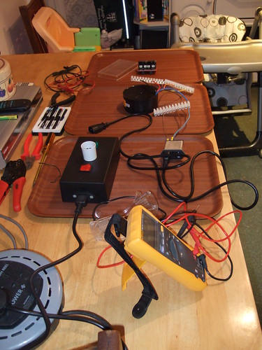
The basic rig.
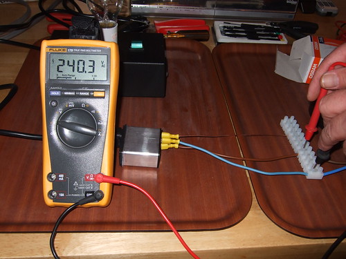
Checking voltage from the power inlet
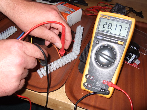
Checking voltage from the transformer
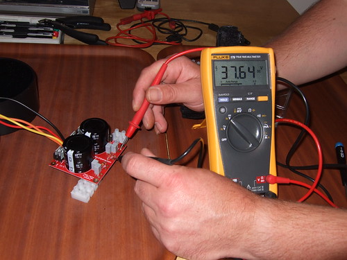
Checking voltage from the power supply board
I did the use the light bulb tester. But nothing happened i.e. I didn't see it light up. I am assuming that this is good.
The basic rig.
Checking voltage from the power inlet
Checking voltage from the transformer
Checking voltage from the power supply board
I did the use the light bulb tester. But nothing happened i.e. I didn't see it light up. I am assuming that this is good.
- Status
- This old topic is closed. If you want to reopen this topic, contact a moderator using the "Report Post" button.
- Home
- Amplifiers
- Chip Amps
- First Lm3886