AndrewT said:I bought 50 temperature switches for the same purpose.
What do you think of my rationale regarding the STO-170? Right temperature? Right placement?
Stuey said:Yes, from memory the amp board has 'Out' and 'OG' (output ground) or something like that? 'Out' is to the inner terminal on the socket and 'OG' is to the outer. Subject to memory confirmation of the markings...Stuey
Oops...that should be Input and SG (signal ground) or whatever the equivalents are on the boards.
I even occasionally have trouble remembering work colleagues names since I had brain surgery last year.
I think over temperature switching is overkill unless you're into partying. I probably won't implement it on mine even though the speaker protection module has it. However, as you've noticed Andrew is far more scientific and analytical on these things and uses them, so given the full house build of yours, go for it.
Stuey
Are these the style you're after?
http://www.jaycarelectronics.co.uk/productView.asp?ID=ST3821&CATID=23&form=CAT&SUBCATID=620
Stu
http://www.jaycarelectronics.co.uk/productView.asp?ID=ST3821&CATID=23&form=CAT&SUBCATID=620
Stu
temp switch
http://www.rapidonline.com/Electron...Sensors/Auto-reset-thermal-switches/35569/kw/
I seem to recall mine were well under £1.00
http://www.rapidonline.com/Electron...Sensors/Auto-reset-thermal-switches/35569/kw/
I seem to recall mine were well under £1.00
Starting to order the components for the Loudspeaker Protection & Muting Circuit (ESP P33) and I'm stuck!
The P33 board is powered by the power rails provided by the amp PSU. Given that my transformer is providing 25VAC, I'm assuming that once it's been through the bridge it ends up at around 35VDC.
So, this means I need a relay with coil voltage of 35VDC ? I've had a look on Mouser, Farnel, RS and Rapid and they don't appear to stock them. This suggests I'm not understanding something. Can someone put me straight please?
I've also got a growing concern that the entire circuit will not work with a mono power amp. The P33 board expects inputs from both the left and right amp outputs. Does anyone have experience of using these with dual mono power amps? I be grateful for the reassurance. Unfortunately, I am unable to post the actual schematic due to the limitations placed on me by ESP.
Hi PJPro,
That is the perfect way to think of any project. Always an opportunity to learn and build on.
Besides, it won't go to waste. I just realized that one thing I built that I still use was constructed in 1977 (I date my PCBs). That also means that there are more similar gadgets around here from the same time period.
Yikes! I should maybe update some of these things.
-Chris
PJPro said:So, this means I need a relay with coil voltage of 35VDC ? I've had a look on Mouser, Farnel, RS and Rapid and they don't appear to stock them. This suggests I'm not understanding something. Can someone put me straight please?
You should read http://sound.westhost.com/project33.htm again. It explains that you calculate R6 to drop the difference between your power supply voltage and the relay voltage.
Also, it states that you must use the power rails for the amp you are monitoring for the circuit to always work correctly. In other words, one protection circuit per channel for a dual mono setup. Given your rails should be almost identical in voltage, you might risk it, but that's up to you.
I know it's a lot of research. I spent probably 3 times the hours researching as I did designing and building for each of my projects.
Also, it states that you must use the power rails for the amp you are monitoring for the circuit to always work correctly. In other words, one protection circuit per channel for a dual mono setup. Given your rails should be almost identical in voltage, you might risk it, but that's up to you.
Not 100% sure I understand you.
Your first statement is not true. You can use an auxillary power supply, for example, the one supplying the soft start circuit. As it happens, I am going to use the power rails.
I will have two boards (one per mono amp). Each board can protect a left and right channel....but, clearly, I only need to support one channel in each amp...so I'll use the left channel in each case.
Where's the risk?
I know it's a lot of research. I spent probably 3 times the hours researching as I did designing and building for each of my projects.
Yeah, but it's fun
")
I mentioned in my other thread that I wanted to pull together all the bits and pieces to summarise the way forward. I also thought it would help me understand how I was going to wired all the components together. The picture is below.
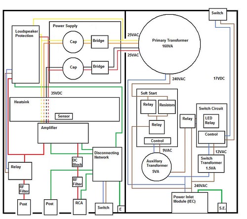
What do you think? Does it look alright? Grateful for any comments.
What do you think? Does it look alright? Grateful for any comments.
I've already had some feedback on the image above....from the upgrade island. Here's a few snippets from that temporary post.
----------------------------
pacificblue
The disconnection network can not only lift the input ground from the chassis. You can also use it to separate that clean input ground from the dirty power and speaker ground, if you connect amplifier power ground and speaker ground directly to the case. For your first tests you should leave the wires long enough to try both configurations.
If you put the RF filter for the speaker output directly behind the amplifier, you also have protection, when the relay is off.
You may need a second RF filter at the amplifier input or move the existing RF filter as close to the amplifier input pins as possible. That way it filters out any disturbances that still enter the wires and traces on the way from the RCA connector to the IC.
Heatsink in the center? Well, if you have enough holes in the case below and above it, and enough distance to the supply capacitors.
wintermute
I took a rather different approach to my LM3886 project I did a P2P. The thread of my (well most of it) journey is here --> [sorry I've lost the damn URL...it's was truncated when I saved it]. There were a few other threads where I asked specific questions before and after starting the build but that pretty much documents the build process
Stuey
PJ, here's a pretty good PDF about ground loops etc. if you have the time to read it!
[Again, the damn url is truncated!]
----------------------------
Don't suppose wintermute and Stuey still have those URLs available?
----------------------------
pacificblue
The disconnection network can not only lift the input ground from the chassis. You can also use it to separate that clean input ground from the dirty power and speaker ground, if you connect amplifier power ground and speaker ground directly to the case. For your first tests you should leave the wires long enough to try both configurations.
If you put the RF filter for the speaker output directly behind the amplifier, you also have protection, when the relay is off.
You may need a second RF filter at the amplifier input or move the existing RF filter as close to the amplifier input pins as possible. That way it filters out any disturbances that still enter the wires and traces on the way from the RCA connector to the IC.
Heatsink in the center? Well, if you have enough holes in the case below and above it, and enough distance to the supply capacitors.
wintermute
I took a rather different approach to my LM3886 project I did a P2P. The thread of my (well most of it) journey is here --> [sorry I've lost the damn URL...it's was truncated when I saved it]. There were a few other threads where I asked specific questions before and after starting the build but that pretty much documents the build process
Stuey
PJ, here's a pretty good PDF about ground loops etc. if you have the time to read it!
[Again, the damn url is truncated!]
----------------------------
Don't suppose wintermute and Stuey still have those URLs available?
Last edited:
Not 100% sure I understand you.
Your first statement is not true. You can use an auxillary power supply, for example, the one supplying the soft start circuit. As it happens, I am going to use the power rails.
I will have two boards (one per mono amp). Each board can protect a left and right channel....but, clearly, I only need to support one channel in each amp...so I'll use the left channel in each case.
Where's the risk?
I don't know, I'm just following the instructions from the manufacturer. From the ESP website:
The power supplies (+ve and -ve) shown in these diagrams will normally be the power amp supply rails. Do not try to substitute different supplies unless you know exactly what you are doing, or the circuit may not work properly. This is especially true of the muting circuit, but incorrect supplies will (may) also affect the DC detection circuit. Like most of my projects, this is intended for experienced constructors.
Yeah, but it's fun
I think so too
I must say, I don't think I would have the patience for a first project of this scale. It's quite impressive. 
Fair enough. There are a few more details (not many) on the secure site. To double check I emailed Rod directly. Here's his reply......I don't know, I'm just following the instructions from the manufacturer. From the ESP website:
P33 works fine with only one input - the other is simply ignored. Powering it from the P39 is not a problem - +/-12V is available from the board.
So, it would appear to be OK. Unfortunately, I had already ordered my components before he had responded....and I got a relay with a 24V coil.
I think so too
Why, thank you. It's a collaborative effort!
Well. All the stuff has been delivered....and there's a ton of it! And it's all been a bit expensive. Lets hope I can get it to work
I'll let you into a secret. I've also ordered the components for my first upgrade.....the P03A. My intention is to have two amps per case, running in bridged mode. But it's a project for another day.....once the chip amps have had a good bit of use and I haven't another project to keep me busy e.g. the SSMH kit has arrived and I'd also like to build a pre-amp (aikido?) and possibly a DAC (buffalo?). The b22/s22 combo looks nice and.....I could go on.....
I'll let you into a secret. I've also ordered the components for my first upgrade.....the P03A. My intention is to have two amps per case, running in bridged mode. But it's a project for another day.....once the chip amps have had a good bit of use and I haven't another project to keep me busy e.g. the SSMH kit has arrived and I'd also like to build a pre-amp (aikido?) and possibly a DAC (buffalo?). The b22/s22 combo looks nice and.....I could go on.....
- Status
- This old topic is closed. If you want to reopen this topic, contact a moderator using the "Report Post" button.
- Home
- Amplifiers
- Chip Amps
- First Lm3886