Looking forward to getting access to those pages.....Stuey said:......You'll get access to the ESP secure site once you've ordered. The page for Project 39 has VERY comprehensive info, including a very clear drawing of how to wire it up to the switch and IEC socket.
Re: Re: Sorry 3.3uF cap is NOT a lowpass at RF
this posting from Infinia was a reponse in answer to my post where Infinia became convinced I had made some kind of error in my advice.
It was specifically written to make my writing appear foolish.
Do not try to extract from the wording used any useful practices for your own use.
It was directed to me and should be read in that context.
Hi PJ,PJPro said:
OK. So the large cap on its own isn't going to provide a RF filtering solution.
So I'd need a ferrite bead in series with the large cap? What does LS mean? Sorry for not knowing this.
Thanks. Hopefully, with advice from yourself and others, it'll be safe and sound good too.
this posting from Infinia was a reponse in answer to my post where Infinia became convinced I had made some kind of error in my advice.
It was specifically written to make my writing appear foolish.
Do not try to extract from the wording used any useful practices for your own use.
It was directed to me and should be read in that context.
PJ,
things are getting very complicated.
Your build is becoming a labour of love.
It will take you a long time, it is costing you a lot of money partly because your Bill of Materials (BOM) is being added to ad infinitum.
I suggest you stop and rethink your build strategy.
1.) build a simple prototype fixed to a piece of chipboard.
2.) fit the absolute minimum to get a chip amp working. No nice to have add ons.
3.) power up this single channel with everything exposed, but keep the pets/children locked up/out.
4.) listen to it powering one channel for an extended series of listening sessions including background music as well as specific Audio events.
5.) decide if a £4 chipamp deserves the £hundreds spent on all the paraphernalia you are accumulating.
Maybe your targets will change after you have built your first prototype, or maybe you will spends dozens of hours casing up your project.
I'd suggest you make this final decision after you have heard the chipamp playing in the typical usage you intend to use it.
Yes. It had occurred to me that I might be turd polishing.
The saving grace is my ultimate plans to upgrade the chipamp and power supply for discrete units (as you recommended earlier). So, all the bits can be reused. I will not skimp on safety and most of the additions relate to this crucial aspect of the build.
But yes. Thanks. Your advice is duly noted.
The saving grace is my ultimate plans to upgrade the chipamp and power supply for discrete units (as you recommended earlier). So, all the bits can be reused. I will not skimp on safety and most of the additions relate to this crucial aspect of the build.
But yes. Thanks. Your advice is duly noted.
Hi PJPro,
Thank you, you have done a fair amount of work getting those links together. You also have your answer already from other members on that inductor.
The advice that AndrewT is giving you is excellent. I have often advised people to do the same thing. Get it running before trying changes that are supposed to make it sound better. I would view the protection relay as a required part, no surprise to those who read my posts.")
Once you have things running along, you can try some suggestions and part changes. I would leave all parts in that are in the app note. They were designed in for a reason and far be it for anyone but an expert to second guess the people who designed the chip.
As far as " It had occurred to me that I might be turd polishing", you never know. ICs and general circuitry have come a great long way since I was starting out. The cheaper stuff in my time sounded truly horrid. The "cheap" chip amp projects sound so much better these days that I feel your amp will have worth. So, if you don't care for it as a main system, it will be a killer computer speaker amp. My home is filled with amplifier experiments that sound good, but not great. My friends and kids have benefited from my experiments as well. What can be improved to you may sound like magic to someone else. You can only judge from what you have heard so far.
The building of a project has far more value than the item it may become. To put it another, over used way, "the trip is worth more than the destination". I have many things I built in the 70s that still work. My kids are amazed when they figure out I was their age when I did these things. I was just surprised to see them.
-Chris
Thank you, you have done a fair amount of work getting those links together. You also have your answer already from other members on that inductor.
The advice that AndrewT is giving you is excellent. I have often advised people to do the same thing. Get it running before trying changes that are supposed to make it sound better. I would view the protection relay as a required part, no surprise to those who read my posts.
Once you have things running along, you can try some suggestions and part changes. I would leave all parts in that are in the app note. They were designed in for a reason and far be it for anyone but an expert to second guess the people who designed the chip.
As far as " It had occurred to me that I might be turd polishing", you never know. ICs and general circuitry have come a great long way since I was starting out. The cheaper stuff in my time sounded truly horrid. The "cheap" chip amp projects sound so much better these days that I feel your amp will have worth. So, if you don't care for it as a main system, it will be a killer computer speaker amp. My home is filled with amplifier experiments that sound good, but not great. My friends and kids have benefited from my experiments as well. What can be improved to you may sound like magic to someone else. You can only judge from what you have heard so far.
The building of a project has far more value than the item it may become. To put it another, over used way, "the trip is worth more than the destination". I have many things I built in the 70s that still work. My kids are amazed when they figure out I was their age when I did these things. I was just surprised to see them.
-Chris
Thanks anatech.
As I said, I feel that I have identified all the bits I need and am in the process of ordering them. It's all good fun, even if it's working out a lot more expensive than I originally estimated. Still, if a jobs worth doing......
My only real concern is that the more components I add, the harder it will be to trace and identify a fault, should it occur. I guess the best method to counter this is to be extra thorough when putting it all together.
Oh. The boards and mosfets from AMB Labs arrived this morning. Excellent quality and a worthy addition to the project.
even more reason to build it up as a single channel prototype on an insulating flat panel.PJPro said:My only real concern is that the more components I add, the harder it will be to trace and identify a fault, should it occur. I guess the best method to counter this is to be extra thorough when putting it all together.
Start with the transformer. Add a rectifier. Add some smoothing Add the SIMPLE amplifier. Add the input filtering. Add the mains filtering. Add the DC detect. Add the output relay. Add the .... etc.
Once you have one channel working, then start all over again on the second channel and prove it.
Now work out how to package that 3foot long assembly inside your box.
Only then do you spend the time to get the final look that you want.
hi PJPro,
I'm not sure if it has been mentioned but always measure Vdc offset whenever you do a change to your amp. It should be below 100mV most of the time with chipamps. After that, connect a cheap test speaker and have a listen (and smell).
BTW: It is possible to polish a turd, I saw it on Myth Busters.
regards
Yes. Absolutely. And I'll be using my deluxe light bulb tester all the wayAndrewT said:even more reason to build it up as a single channel prototype on an insulating flat panel.
Start with the transformer. Add a rectifier. Add some smoothing Add the SIMPLE amplifier. Add the input filtering. Add the mains filtering. Add the DC detect. Add the output relay. Add the .... etc.
Once you have one channel working, then start all over again on the second channel and prove it.
Now work out how to package that 3foot long assembly inside your box.
Only then do you spend the time to get the final look that you want.
.Thanks Greg. Will do.Greg Erskine said:hi PJPro,
I'm not sure if it has been mentioned but always measure Vdc offset whenever you do a change to your amp. It should be below 100mV most of the time with chipamps. After that, connect a cheap test speaker and have a listen (and smell).
BTW: It is possible to polish a turd, I saw it on Myth Busters.
regards
I agree that it is possible to polish a turd. But however shiny, it's still a turd.
Regarding the earth discussion:
"a direct mechanical link from the supply earth wire to the metal chassis".
The above, which is what was recommended above is not near good enough in my opinion. I am not trying to be awkward. The above should be something like:
"a direct mechanical link from the supply earth wire to the metal chassis AND to all other conductive elements on the chassis which the user may touch or work with, eg shielded wires, cables, probes, your electric guitar's lead, the electric guitar's strings, bridge and buckles, your amp's metal knobs and so on".
The advice to keep the RCA plugs and other interconnects separated from the earth (to avoid ground loops) kind of breaks it for me, I can imagine plugging a guitar into your amp and getting electrocuted.
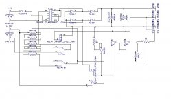
Regrding the slow start circuit, would you like to be a guinea pig ? I have designed one and amabout to build it, the PCB should be arriving soon, it looks like this (I am sure I have posted this before somewhere here). What it does is provides a 12 V on-off switch, so you do not run 240V wires inside the enclosure and onto the front panel (imagine spilling your pint of beer) and additionally a slow start by the means of two relays.
"a direct mechanical link from the supply earth wire to the metal chassis".
The above, which is what was recommended above is not near good enough in my opinion. I am not trying to be awkward. The above should be something like:
"a direct mechanical link from the supply earth wire to the metal chassis AND to all other conductive elements on the chassis which the user may touch or work with, eg shielded wires, cables, probes, your electric guitar's lead, the electric guitar's strings, bridge and buckles, your amp's metal knobs and so on".
The advice to keep the RCA plugs and other interconnects separated from the earth (to avoid ground loops) kind of breaks it for me, I can imagine plugging a guitar into your amp and getting electrocuted.
Regrding the slow start circuit, would you like to be a guinea pig ?
I have designed one and amabout to build it, the PCB should be arriving soon, it looks like this (I am sure I have posted this before somewhere here). What it does is provides a 12 V on-off switch, so you do not run 240V wires inside the enclosure and onto the front panel (imagine spilling your pint of beer) and additionally a slow start by the means of two relays.Attachments
By the way, remember that workshop you found near you to make you an aluminium panel? Do you think they'd be able to construct an alumunium enclosure for my guitar amp? I need an encosure to measure 85 cm across, 40 cm depth, and 7cm height - and such things are hard to find
I thought the network provided this....via the resistor and cap (when all is well) and via the bridge in times of trouble?akis said:Regarding the earth discussion:
The advice to keep the RCA plugs and other interconnects separated from the earth (to avoid ground loops) kind of breaks it for me, I can imagine plugging a guitar into your amp and getting electrocuted.
If I hadn't already bought all the boards, etc, then I'd take you up on your offer. Moreover, I tend to take my time......akis said:Regrding the slow start circuit, would you like to be a guinea pig ?
BTW, the E24 provides 12 VDC for the switch and allows use of momentary-contact switches (see here).
Incidentally, Headwise appears to be back online.
Thanks.
The E24 also provides thermal auto-shutoff. See the quote below from AMB taken from the Headwise forum......
Given the SPiKe protection incorporated into the LM3886, should I bother with this capability or is a belt and braces approach better?
If I do go ahead with the thermal auto-shutoff and, given the operating temperature range of the LM3886 being -20 to 85 degC, should I go for the STO-180 (which opens at 79 to 85 degC) or the STO-170 (which opens at 74 to 79 deg C). My view is to go with the STO-170. Why? Well I'm assuming I would mount the sensor on the heatsink (or chip clamping bar) as close the the chip as possible but not actually on the chip. The lower temperature rating would allow for this distancing from the chip itself.
Thanks for any advice/opinion.
AMB on Headwise said:I must confess that sometimes I am as guilty as anyone when it comes to creeping featurism, but having a relay switching the power provides another opportunity that would integrate well into this circuit without much additional complexity. Namely, amplifier overheat auto-shutoff. Many high-end and pro-grade power amps have this feature, and I thought it would be useful to have it as an option here. Using Stancor disc thermostats (i.e., thermal breakers) mounted on the main heatsinks, they could enable the amp to shut itself off if the temperature exceeds a certain threshold. Thus, I modified the circuit and worked this into the design. It needs the "normally-closed" thermal breakers (those with part numbers beginning with STO-). For my build, I chose the STO-170 which will open when the temperature reaches 170°F (77°C). The breaker will auto-reset when the temperature drops to 30°F (17°C) below the rated threshold.
Given the SPiKe protection incorporated into the LM3886, should I bother with this capability or is a belt and braces approach better?
If I do go ahead with the thermal auto-shutoff and, given the operating temperature range of the LM3886 being -20 to 85 degC, should I go for the STO-180 (which opens at 79 to 85 degC) or the STO-170 (which opens at 74 to 79 deg C). My view is to go with the STO-170. Why? Well I'm assuming I would mount the sensor on the heatsink (or chip clamping bar) as close the the chip as possible but not actually on the chip. The lower temperature rating would allow for this distancing from the chip itself.
Thanks for any advice/opinion.
PJPro said:
I thought the network provided this....via the resistor and cap (when all is well) and via the bridge in times of trouble?
Yes except it is not the same* as a simple, mechanical connection to earth which should cover every bit of metal that protrudes or can be touched during normal operation, and that includes things like instrument leads or interconnects.
* this means there is a whole bunch of electronics in the way, additional PCBs, wires etc, there is additional complication and more things to go wrong, eg imagine if you have a bad solder connection, or the bridge is defective and so on. You'd never know until it was too late.
Also, did you see my question about the aluminium enclosure?
PJPro said:The E24 also provides thermal auto-shutoff. See the quote below from AMB taken from the Headwise forum......
Given the SPiKe protection incorporated into the LM3886, should I bother with this capability or is a belt and braces approach better?
If I do go ahead with the thermal auto-shutoff and, given the operating temperature range of the LM3886 being -20 to 85 degC, should I go for the STO-180 (which opens at 79 to 85 degC) or the STO-170 (which opens at 74 to 79 deg C). My view is to go with the STO-170. Why? Well I'm assuming I would mount the sensor on the heatsink (or chip clamping bar) as close the the chip as possible but not actually on the chip. The lower temperature rating would allow for this distancing from the chip itself.
Thanks for any advice/opinion.
That is a cool feature to have, the ability to sense that something has gone wrong and as a last ditch effort we are switchign off. Except - if you have a proper heatsink, is it theoretically possible to heat it to 75 C ? Do some analysis to see what sort of power you'd need for the given heatsink and whether the chip would have shutdown already before that. Heatsinks have a C/W rating if I remember correctly, and the LM3886 will say how many watts it will allow before one of the trigger conditions makes it switch off, eg shorting the output or driving it with a pure square wave etc. Nah, I think it is not needed, you'd be better off using my board.
I did speak to them about listing aluminium cases on their website. The guy did consider it. He took a look at mine and said it was simply two lengths of extruded aluminium (the sides) with cut plate for the rest........ but I suspect he won't bother. Having said that, I am sure they will fabricate whatever you like. Their workshop is littered with big machinery. Why not give them a ring and see? Their website is here.akis said:By the way, remember that workshop you found near you to make you an aluminium panel? Do you think they'd be able to construct an alumunium enclosure for my guitar amp? I need an encosure to measure 85 cm across, 40 cm depth, and 7cm height - and such things are hard to find
I suspect you'll have to sort out the finishing yourself although anodizers aren't hard to find.
I'd be interested to know what they quote you for the work. I'm considering using them in the future.
akis said:That is a cool feature to have, the ability to sense that something has gone wrong and as a last ditch effort we are switchign off. Except - if you have a proper heatsink, is it theoretically possible to heat it to 75 C ? Do some analysis to see what sort of power you'd need for the given heatsink and whether the chip would have shutdown already before that. Heatsinks have a C/W rating if I remember correctly, and the LM3886 will say how many watts it will allow before one of the trigger conditions makes it switch off, eg shorting the output or driving it with a pure square wave etc. Nah, I think it is not needed, you'd be better off using my board.
Of course you are right. My heatsink is massive and unlikely to reach the trigger temperature before the chip does. That's why I thought I'd place the sensor on the small aluminium bar which I'm going to use to clamp the chip to the heatsink.
- Status
- This old topic is closed. If you want to reopen this topic, contact a moderator using the "Report Post" button.
- Home
- Amplifiers
- Chip Amps
- First Lm3886