Posted the parts list on my wiki
http://www.digilux.net/audio/index.php?title=Tube_Mic_Preamp
Going to order my resisters tonight, then start hunting for the capacitors tomorrow.
http://www.digilux.net/audio/index.php?title=Tube_Mic_Preamp
Going to order my resisters tonight, then start hunting for the capacitors tomorrow.
Ryan,
I saw on your "wiki" that you were having trouble sourcing impedance selecting switches. Mouser Electronics stock number 105-13572 is a Lorlin brand, 2 pole, 2-6 user selectable position, shorting (make before break), part that should do the job for you. The price is $4.33 each.
I saw on your "wiki" that you were having trouble sourcing impedance selecting switches. Mouser Electronics stock number 105-13572 is a Lorlin brand, 2 pole, 2-6 user selectable position, shorting (make before break), part that should do the job for you. The price is $4.33 each.
Mic input transformers
It would be a help to get a mic input transformer that mounts in a single round hole like these:
http://cgi.ebay.com/ws/eBayISAPI.dll?ViewItem&rd=1&item=190165773668&ssPageName=STRK:MEWA:IT&ih=009
That way you can loosen the nut and then orient it for lowest HUM and then tighten it down. Especially if the power transformer is on the same chassis. This is harder to do with a four point or less screw mount. Jensen makes such a shielded tranny. It has a special ending on the stock number. These Beyer transformers turn up occasionally on ebone. Microtran also made some good ones. The most important thing in a mic transformer is the shielding to -60dbv. An output transformer doesn't have to be shielded because the level is way up out of the noise above 0dbv. You could use a secondary as low as 10K for the mic input if you are not going to use the Triad original or the UTC A series. Modern winders don't like to wind high turns ratio audio trannys like to50,000 ohms because it increases the harmonic distotion of the transformer. Ray Hughes
Deals on ebone
Ryan: Don't know if you've looked but you can find power supplys that are already assembled and ready to go for filament and phantom power. These are made by POWER ONE and by CONDOR. Look for a linear power supply rather than a switcher. The 5v-3 amp supply would be fine for filaments. It has OVP over voltage protection and it can be turned up to 6 volts/ The OVP can be set higher.
http://cgi.ebay.com/Condor-Power-Su...ryZ58288QQrdZ1QQssPageNameZWD1VQQcmdZViewItem Also the 48 volt power supply can power a whole studio of microphones;
http://cgi.ebay.com/CONDOR-HD48-3-A...ryZ58286QQrdZ1QQssPageNameZWD1VQQcmdZViewItem
That leaves only the B+ voltage that you need to worry about. Power One and Condor also make high voltage supplys for your B+ but they seldom come up on ebone. Using these power supply might take a larger chassis or you can locate these about 4 feet away from your tubes. Just a few thoughts that may make the project a little easier. Ray Hughes
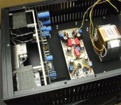
Second the prefab supply route. I just finished a mono mic preamp using a 170V/120mA supply and a 25V supply from International Power (got 'em from Mouser). Good, quiet, reliable linear supplies. You can get a little creative with re-packaging them if you ditch the original chassis (see photo).
Good luck!
Good luck!
Attachments
here's a mic preamp I'm half way through building., it's just about as simple as possible.Eli Duttman said:Assuming a "mike" preamp is the object of your desire, I strongly suggest you find a different circuit.
It's intended to use a L7824 regulator to provide the phantom power, and run the valve heaters in series. On sim it gives exceptional performance for so few parts!

Merlinb said:
here's a mic preamp I'm half way through building., it's just about as simple as possible.
It's intended to use a L7824 regulator to provide the phantom power, and run the valve heaters in series. On sim it gives exceptional performance for so few parts!
Hi Merlinb,
I did built something with very similar front end and ended up discarding it.
The problems were:
1) Noise. I tried a low noise version of ECC83--Telefunken ECC808 (different pinout), but it did not help much.
2) In order to overcome 1) I put an input transformer wired as 1:4 and got into overloading problems, when there was impossible to use with condenser mics.
Also looking at your schematics the 24V with 6.8K resistors won't work. If you increase the current (decrease the resistors values) it could work with SOME mics. There are however many mics on the market without DC convertor for capsule bias and as a result you'll get very limited sensitivity and degraded sound.
As a side note, I am not a big fan of changing gain by means of changing of NFB.
Marik said:
Also looking at your schematics the 24V with 6.8K resistors won't work. If you increase the current (decrease the resistors values) it could work with SOME mics. There are however many mics on the market without DC convertor for capsule bias and as a result you'll get very limited sensitivity and degraded sound.
As a side note, I am not a big fan of changing gain by means of changing of NFB.
6.8k seems to be the industry standard for feed resistor, from what I can tell. Since I'm running 24V, do you think 3.3k would be a better choice?
I have not heard of any mics that won't work well from voltages lower than 48V, at least not from any of my sound engineer friends. I was under the impression that the 48V spec is a historical thing, and also used to power some more esoteric DI boxes etc.
I am surprised you had noise problems from a triode. Even the crappy ECC83 with its low gm has an equivalent noise resistance of less than 10k...
I know some people don't like variable feedback, but I'm an advocate myself (where valves are concerned at least.) Plus it seemed the easiest way of doing it in this small circuit, granted it wouldn't be appropriate for professional stuff.
What's a smoke test?
Re: Merlinb
When you cathode couple any device be it transistor, tube or FET, you're up against Boltzman's constant. The Johnson shot noise will be multiplied by .707 or the reciprocal of the square root of 2. This will make a diff amp a noisy choice for a first stage in a transducer amp whose input must deal with a voltage in the -57dbv range. Also it likes to be kept symmetrical, balanced in, balanced out to do it's best job. I built a very similar preamp but had to cast it aside for too much equivalent input noise. A diff amp works best for an input of a line amp where the signal is way up out of the noise. The choice of the 12ax7 would be my last, noise wise. Maybe in 1959, in my youth, but not today. A 12ay7 is much less noisier and much better made and balanced from side to side. It also has a unique blend of transconductance to plate resistance. Also input transformer coupling would offer a much lower equivalent input noise figure.
Balancing this for CMRR with those feedback pots would be a pain! That negative tail voltage CCS on the cathodes of the input stage must be very well filtered for ripple will be amplified if it gets on the cathodes.
Cathode followers are another problem. Their square wave turn off time is MUCH slower than their (turn on) rise time. You get this deep curve to the down turn off signal. A White cathode follower would be better but a push pull transformer coupled output stage would be even better IMHO.
Re: Re: Merlinb
Without wishing to hijack this thread; clueless newbie here, and I was just wondering what's the electrical cause/reason for this above behavior?grhughes said:Cathode followers are another problem. Their square wave turn off time is MUCH slower than their (turn on) rise time.
Quasi answer to cathode follower question
As I was told by someone smarter than I, cathode followers act like capacitor charge-dischargers. You have to use a capacitor on the output to block DC offsets. Choosing a proper capacitor for good frequency response/output impedance works against this charge-discharge behavior. They also without a negative bias voltage won't go negative fast at all.
As I was told by someone smarter than I, cathode followers act like capacitor charge-dischargers. You have to use a capacitor on the output to block DC offsets. Choosing a proper capacitor for good frequency response/output impedance works against this charge-discharge behavior. They also without a negative bias voltage won't go negative fast at all.
Merlinb said:
6.8k seems to be the industry standard for feed resistor, from what I can tell. Since I'm running 24V, do you think 3.3k would be a better choice? I have not heard of any mics that won't work well from voltages lower than 48V, at least not from any of my sound engineer friends. I was under the impression that the 48V spec is a historical thing, and also used to power some more esoteric DI boxes etc.
The 6.8K is a standard, which was accepted long time ago and BTW, currently being reconsidered.
Ideally, it can deliver 48V/3.4K=14ma max current. According to the standard, with 24V phantom the current should be doubled.
Re: Re: Merlinb
Er, but by that logic the noise must surely be reduced then? By 30% or so... In any case, a random percentage of that noise will actaully be common mode, so things aren't quite as pessimistic as you suggest!
A white follower would be good yes, but ideally would need a higher HT than I have available, and a lot more chassis space than I have! Also, a CFs ability to drive a square wave is only compromised when it's driving a reactive load, and in this case I'm assuming the following amp/mixing desk etc. isn't significantly reactive except at HF, where I no longer care.
grhughes said:The Johnson shot noise will be multiplied by .707 or the reciprocal of the square root of 2.
Er, but by that logic the noise must surely be reduced then? By 30% or so... In any case, a random percentage of that noise will actaully be common mode, so things aren't quite as pessimistic as you suggest!
Well I've done that (though I added the phono out just for kicks)Also it likes to be kept symmetrical, balanced in, balanced out to do it's best job.
I agree with that, but I'm working with what I've got. Plus I was interested to see just what you can do (or not do!) with an ECC83. Plus 12AY7s are a bit uncommon in Britian.The choice of the 12ax7 would be my last, noise wise. Maybe in 1959, in my youth, but not today. A 12ay7 is much less noisier and much better made and balanced from side to side.
Well that much is obvious. But I'm damned if I'm paying for one!Also input transformer coupling would offer a much lower equivalent input noise figure.
Ah, but if the PSU is well regulated then I don't need perfect CMRR. Also, I've actually switched to a stepped attenuator. (yeah, even I gave up on a pot!) And if you think I'm using matched triodes then I'm afraid I shall have to dissapoint...Balancing this for CMRR with those feedback pots would be a pain!
Not a problem, it's fed from the phantom power regulator. I suppose a cap across the diodes might be in order though. Well shall see.That negative tail voltage CCS on the cathodes of the input stage must be very well filtered for ripple will be amplified if it gets on the cathodes.
Well I'm not using a tranny,because I'm poor, and I enjoy a challenge.Cathode followers are another problem. Their square wave turn off time is MUCH slower than their (turn on) rise time. You get this deep curve to the down turn off signal. A White cathode follower would be better but a push pull transformer coupled output stage would be even better IMHO.
A white follower would be good yes, but ideally would need a higher HT than I have available, and a lot more chassis space than I have! Also, a CFs ability to drive a square wave is only compromised when it's driving a reactive load, and in this case I'm assuming the following amp/mixing desk etc. isn't significantly reactive except at HF, where I no longer care.
Well the IEC states a max current draw for any mic as 10mA, so I suppose I should be ok with 4.7k feed resistors then.Marik said:
The 6.8K is a standard, which was accepted long time ago and BTW, currently being reconsidered.
Ideally, it can deliver 48V/3.4K=14ma max current. According to the standard, with 24V phantom the current should be doubled.
Re: Re: Re: Merlinb
They can source current into a reactive load quite easily from the HT, but must sink it through the cathode resistor, which is quite large.Majestic said:Without wishing to hijack this thread; clueless newbie here, and I was just wondering what's the electrical cause/reason for this above behavior?
Merlinb said:
Well the IEC states a max current draw for any mic as 10mA, so I suppose I should be ok with 4.7k feed resistors then.
According to the standard, for the 24V that should be 3.4K.
Let's say, you've got something like Earthworks with current draw of 9mA. Just calculate what is your voltage drop gonna be if you going with 10mA
.BTW, personally, I'd go with 48V.
Re: Re: Re: Re: Merlinb
Is this something that standing on a CCS would fix? (Would a negative supply even fix it??)Merlinb said:They can source current into a reactive load quite easily from the HT, but must sink it through the cathode resistor, which is quite large.
- Status
- This old topic is closed. If you want to reopen this topic, contact a moderator using the "Report Post" button.
- Home
- Live Sound
- Instruments and Amps
- First DIY job: Dual Tube Recording Preamp