dantwomey said:
This appears to be the correct datasheet.
What I 'think' this transistor does is 'regulate' the 8V supply down to 5V for the circuits that require this voltage.
Regards,
Dan
It's an external pass transistor for the chip based regulator circuit. The transistor is inside the regulator error amplifier feedback loop.
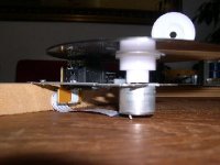
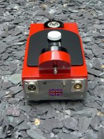
Erik van Voorst said:The weight of 1 gram in action....(if you build one yourself try to lift the weight and notice how the sound changes.)...
Interesting Erik, I wonder if this external force acting on the sled is reducing backlash in the gear train, if such were the case it might make the sled drive servo work less hard, and reduce tracking servo activity as well. Worth trying I think. I've ordered the cd clamp and will try this upgrade in conjunction with that. (sequentially)
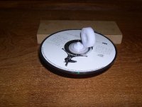
Yes I have tried it out with a "failure" Clearaudio Delrin puck (exentric)
I removed the original plastic platform with a dremel (small drill with a cutting wheel) because with bare hands I think it will be
risky to do damage in my opinion.
I made from a small piece of wood an exact measure between mounting platform and cd. (approx. a tenth of a small pencil)
I used my drill chuck to slowly press it home...till the cd hits the wood....
The part with the drill chuck still bothers me because there is a load of preasure......
When Roy sends me a proper puck I will use a diffrent method")
Beware there is a snag...it is after mounting impossible to reach the 2 small screws...so mount it on your final rig
I removed the original plastic platform with a dremel (small drill with a cutting wheel) because with bare hands I think it will be
risky to do damage in my opinion.
I made from a small piece of wood an exact measure between mounting platform and cd. (approx. a tenth of a small pencil)
I used my drill chuck to slowly press it home...till the cd hits the wood....
The part with the drill chuck still bothers me because there is a load of preasure......
When Roy sends me a proper puck I will use a diffrent method
Beware there is a snag...it is after mounting impossible to reach the 2 small screws...so mount it on your final rig
Attachments

If you enjoy more detail pics you can look at the dutch forum...
http://www.htforum.nl/yabbse/index.php?topic=76211.0
Attachments

I just like to know that I have tried everything to get the most out of this design...It is definetely worth it.
I think there is still room for improvement...the major asset being that we can LISTEN to it step by step in our own configuration...also you do not have to do it all at once....
If you are in the mood and have some money for the hobby you can try the next step....
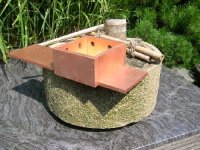
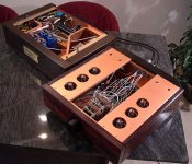
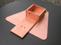
I had all the copper as a left-over from building my pre-amp.....I got at the right moment loads of it against a reasonable price via a client/friend..
I think there is still room for improvement...the major asset being that we can LISTEN to it step by step in our own configuration...also you do not have to do it all at once....
If you are in the mood and have some money for the hobby you can try the next step....
I had all the copper as a left-over from building my pre-amp.....I got at the right moment loads of it against a reasonable price via a client/friend..
Attachments
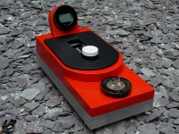
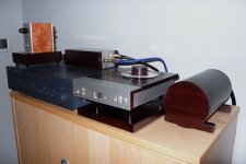
I finaly got to it to put all the stuff -minus the audio board- and put it on a piece of wood for easy tweaking.
I tried to recycle the old power section, but somehow its only getting me +15 volt, on the 12v line...
No 8 volt anywhere. I tried linking the b+ and dc+ the same as the switch between battery power and wall power, but didn`t help.
Basicly this is what I have now:
-Power input 230 volt to the transformer (battery switch bridged)
-12volt ac from transformer into the power board
-no connectors connected to any connectors at the small board
-15 volt dc at the 12 volt place on the power connector
-no 8 volt anywhere
anyone got any idea`s?
As I thought was possible, was just take 8volt and hook it up to the transport. Then all I need to connect the ribbonconnector to the lcd pcb... or?
Not a good start of a project
rikkert1978 said:I finaly got to it to put all the stuff -minus the audio board- and put it on a piece of wood for easy tweaking.
I tried to recycle the old power section, but somehow its only getting me +15 volt, on the 12v line...
No 8 volt anywhere. I tried linking the b+ and dc+ the same as the switch between battery power and wall power, but didn`t help.
Basicly this is what I have now:
-Power input 230 volt to the transformer (battery switch bridged)
-12volt ac from transformer into the power board
-no connectors connected to any connectors at the small board
-15 volt dc at the 12 volt place on the power connector
-no 8 volt anywhere
anyone got any idea`s?
As I thought was possible, was just take 8volt and hook it up to the transport. Then all I need to connect the ribbonconnector to the lcd pcb... or?
Not a good start of a project
Looking at the schematic it's hard to see where you could go wrong. If necessary I could hook up a spare PS here and see what I get.
Regards,
Dan
An externally hosted image should be here but it was not working when we last tested it.
Thought I'd post a photo of my finished Shigaclone and say a big thank you to Peter Daniels for starting this project. Thanks also to all the other contributors to this thread. I've learned so much –– and my system has taken a quantum leap in sound quality.
Cheers,
Malcolm
Cheers,
Malcolm
Attachments
- Home
- Source & Line
- Digital Source
- Finally, an affordable CD Transport: the Shigaclone story