dantwomey said:
You have me puzzled here. I'm building a separate clock (KC7) with it's own independent PS.
dantwomey -
Sorry - poor explanation on my part. With separate clock and PS you remove the original ceramic resonator and connect as described by Peter in post 1420.
Puffin - I can't exactly tell from your pics where the actual crystal is located.

jonners. in the first picture the crystal is the silver part on the right at the end of the board. I have wired it as suggested by Audio1st, but it does not read the TOC correctly and then spins very slowly.
http://www.diyaudio.com/forums/attachment.php?s=&postid=1468077&stamp=1206637320
The flea is only giving out 5v is that enough
http://www.diyaudio.com/forums/attachment.php?s=&postid=1468077&stamp=1206637320
The flea is only giving out 5v is that enough
Puffin said:jonners. in the first picture the crystal is the silver part on the right at the end of the board. I have wired it as suggested by Audio1st, but it does not read the TOC correctly and then spins very slowly.
Can you describe or give a link showing the clock circuit that you are using the crystal in?
jonners. Ignorance is probably my downfall. I don't think that what I am trying to do is a "clock circuit". I may be trying to do something that I can't (if you see what I mean)
This I assume is proper re-clocking board (Trichord)
http://www.diyaudio.com/forums/attachment.php?s=&postid=1564813&stamp=1216401853
I removed the crystal and attached it to the flea to give it it's own PS. I am now trying to attach if from where I removed it i.e to the two points on the board. I assume that the board has it's own clock circuit to power the Crsytal. Does Audio1st's suggestion only work if you use a re-clocking circuit?
Puffin said:
Does Audio1st's suggestion only work if you use a re-clocking circuit?
That's right. I think you are indeed trying to do something that can't work. You need to either connect the crystal directly to the board as a replacement for the original ceramic resonator (thus using the board's own clock circuit), or you use an external clock and PS connected as described by Audio1st and Peter.
jonners. Nothing ventured and nothing gained at present!
However, I thought I would attempt the flea as I had all the bits to put it together. I was amazed that it worked. So, as it was intended with to be used with the Tent ""CLOCK"I will obviously need to get one!
I have ordered one of the cheapo clock boards (£20) from ebay mentioned in this thread somewhere, to see what it is like.
As I now have a spare flea clone, does anyone know if this could be used to power the existing clock circuit in the Shigaclone? If so where would be inserted.
I have just read this :-
Referring to page 16 of service manual: http://www.ferdsaudio.com/RC-EZ31.pdf
8V is connected right after choke L901 (the choke is recommended to be removed).
There is also 5V supply, based on Q902. If you want to use one super regulator you should probably start with 5V supply; in that case remove transistor Q902 and connect 5V wire from regulator to collector pad, the ground from regulator connects to negative pin of C916. You can also cut the trace from collector output (Q902) and connect external 5V there (that's why you see black wire jumper in some of my pics).
You may also consider 8V super regulator and this would connect right after choke (L901)
Presumably I could use the flea as described here?
Puffin said:
Presumably I could use the flea as described here?
Maybe not. The flea, being flea-power, will only supply a max. of 30mA. I'm not sure what current the board will consume, but I think it's likely to be more.
jonners said:
Maybe not. The flea, being flea-power, will only supply a max. of 30mA. I'm not sure what current the board will consume, but I think it's likely to be more.
The clock circuit in the stock setup is integral with the LC78601 DSP IC which I believe uses significantly more than 30mA. (data sheet not currently to hand) Not only this but the ASP should be powered off of the same supply to prevent issues with logic levels between the two ics.
This morning I ordered 2 more super regulators...I will try them out ..one for the clock en one for the motor.....if it proves to be
disapointing to use on the clock I will give the NC PSU from Trichord themselves a try...
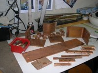
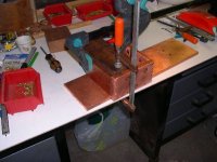
Today I took the entire day working on the copper enclosure....
details on the dutch forum...sorry
disapointing to use on the clock I will give the NC PSU from Trichord themselves a try...
Today I took the entire day working on the copper enclosure....
details on the dutch forum...sorry
Attachments
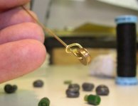
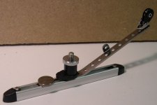
...a couple of days ago I made (with my friend ofcourse) a kind of weight compensation for the laser transport to solve the resonance and the free-friction on it...
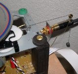
Remarkable how it influences the sound for the better....by increasing the weigt you are able to "voice" ...it speaks for itself that this will continue as my final tweak....however I could not resist to build a more versatile crane for the final enclosure...
The foto shows a contraption made out of brass wire and a part from my miniature boating articles...quickly made to good use to give it a try...
The idea comes from Cees Pel (years ago) a very good friend of Wilco (VOID) who explained the boombox laser theory.
They have a 5 year further development of the Shigaraki on their resume..
Attachments

jonners said:
Maybe not. The flea, being flea-power, will only supply a max. of 30mA. I'm not sure what current the board will consume, but I think it's likely to be more.
Just out of curiosity I measured the current draw of the Shig. On startup it peaks briefly at 450ma and then settles in to 200-210ma DC while running. This was measured at the output of the 8v supply.
Regards,
Dan
This appears to be the correct datasheet.Puffin said:Q902 is where it is suggested that a super regulator be used.
The Q902 is a B764 regulator. It says that Collector to Emitter Saturation voltage is IC 500ma and IB=50ma. Base to Emitter figures are the same.
Anyone know what the figures mean?
What I 'think' this transistor does is 'regulate' the 8V supply down to 5V for the circuits that require this voltage.
Regards,
Dan
- Home
- Source & Line
- Digital Source
- Finally, an affordable CD Transport: the Shigaclone story