All done with #1
My stock Shiga is all done. I've been running it for about 30 hours now in my system. I won't say it beats my Proceed PDT-3, but it's surprisingly good for the money. Besides, this is going to be my control for the next one.
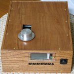
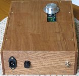
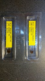
A couple of pics of the finished item. No, I'm not a very good woodworker , but I think it came out okay.
My stock Shiga is all done. I've been running it for about 30 hours now in my system. I won't say it beats my Proceed PDT-3, but it's surprisingly good for the money. Besides, this is going to be my control for the next one.
A couple of pics of the finished item. No, I'm not a very good woodworker
, but I think it came out okay.Attachments
Small observation. After the player has been on for a very long time (days), in my case the Search Forward and Reverse (SF, SR) stopped working. I've been burning in my Shiga playing a CD 24/7 over the last number of days. When I was using it today to listen to music I noted that the SF and SR wouldn't work from the remote. It just skipped to either the next track or the previous. Powering off the Shiga and back on fixed it. Looks like there's some sort of bug in the controller code.
Hi guys, where can I buy the new TIBI shigaclone? Is it as good as the "original" shigaclone?
vicol audio : Webshop
Don't know the answer to the comparision as I didn't build the original shigaclone, but I bet the Tibi version is just as good, if not better.
OK correct buttons now ")
I measured the output of the shigaclone with my scope...
The input is indeed above the industry standard of 0,5V actually measuring around 1,6V peak to peak with the T pad in place. It s probably a bit higher with no shunt parts installed.

Which brings the required attenuation to around -10dB or a bit more if we account for the shunt parts that were present during the measurement.
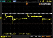
In the output of my 75R 12dB T pad, the signal looks like this, which is far from what I was expecting to see...
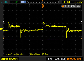
The so called "square" sits at around 100mV peak to peak which is pretty damn lower than expected...
So perhaps we need to reevaluate a bit our thoughts about the attenuation needed? Perhaps digital square stuff behave quite differently than plain DC...? Perhaps we were looking at a completely wrong place and actual audio nirvana sits somewhere between -5 and -10db?
I need to follow Fran's advice and try 6dB and 10dB attenuators as well.
I was also curious if increasing the left side impedance to chip recommendation levels could make the square look more... square... and how this could affect the sound... That s probably very dac-side dependent...
I measured the output of the shigaclone with my scope...
The input is indeed above the industry standard of 0,5V actually measuring around 1,6V peak to peak with the T pad in place. It s probably a bit higher with no shunt parts installed.
Which brings the required attenuation to around -10dB or a bit more if we account for the shunt parts that were present during the measurement.
In the output of my 75R 12dB T pad, the signal looks like this, which is far from what I was expecting to see...
The so called "square" sits at around 100mV peak to peak which is pretty damn lower than expected...
So perhaps we need to reevaluate a bit our thoughts about the attenuation needed? Perhaps digital square stuff behave quite differently than plain DC...? Perhaps we were looking at a completely wrong place and actual audio nirvana sits somewhere between -5 and -10db?
I need to follow Fran's advice and try 6dB and 10dB attenuators as well.
I was also curious if increasing the left side impedance to chip recommendation levels could make the square look more... square... and how this could affect the sound... That s probably very dac-side dependent...
Attachments
Last edited:
OK after a rough day, I m relaxing with some proper measurements this time... for some silly reason I did the previous measurements with the mid of the T as the ground reference...
So here we go:
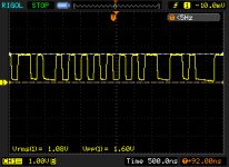
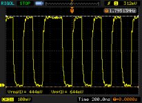
This is the image before the attenuator. The peak to peak is actually 2.56V which actually verifies my fears that the DMM experiments were averaging the voltage a bit.
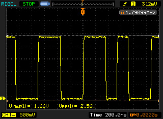
And this is the image of the signal after the attenuator.
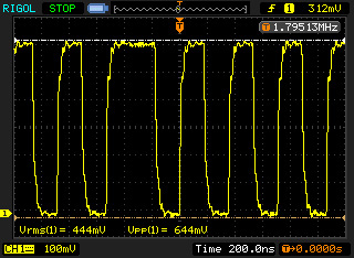
It is 0,65V which almost perfectly 12db lower than the input Vpp, which also verifies that I did not screw up the attenuator and that I was talking bs when suggesting that high frequency digital signals could behave differently in that aspect than DC....
This also suggests that an attenuation of around 14.2dB will also be more appropriate if we are after the industry standard of 0.5V.
The rise time also seems a bit slowish. Seems to be around 60ns. Again, I wonder how could this be affected by an easier impedance load to the chip and how this could affect the sound.
I have also measured the 7808 and salas outputs.
The 7808 driving the motors only seems to behave pretty well with almost 7mv noise... I bet I can make these go even lower with shorter and better motor cabling, and some caps in the spindle motor.
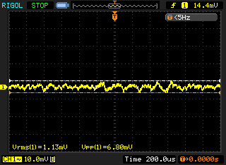
Salas seems to be having some trouble with the digital stuff though...
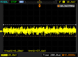
Peak to peak noise is about 40mV. I bet I can do better than that with shorter cables and some minor adjustments to the output caps
So here we go:
This is the image before the attenuator. The peak to peak is actually 2.56V which actually verifies my fears that the DMM experiments were averaging the voltage a bit.
And this is the image of the signal after the attenuator.
It is 0,65V which almost perfectly 12db lower than the input Vpp, which also verifies that I did not screw up the attenuator and that I was talking bs when suggesting that high frequency digital signals could behave differently in that aspect than DC....
This also suggests that an attenuation of around 14.2dB will also be more appropriate if we are after the industry standard of 0.5V.
The rise time also seems a bit slowish. Seems to be around 60ns. Again, I wonder how could this be affected by an easier impedance load to the chip and how this could affect the sound.
I have also measured the 7808 and salas outputs.
The 7808 driving the motors only seems to behave pretty well with almost 7mv noise... I bet I can make these go even lower with shorter and better motor cabling, and some caps in the spindle motor.
Salas seems to be having some trouble with the digital stuff though...
Peak to peak noise is about 40mV. I bet I can do better than that with shorter cables and some minor adjustments to the output caps
Attachments


Easy AES/EBU ??
Thank you so much for this!
For those of us who have a DAC with an AES/EBU input, this seems to open up an interesting possibility. The AES3 (AES/EBU) standard allows peak to peak voltage in the range of 2 to 7 volts. It seems like setting up a balanced, 110 ohms connection without attenuation would allow the output to go directly to the DAC. I think this would only require a couple of 110 ohm series resistors, one in the signal side and one on the return side.
Am I missing something?
This is the image before the attenuator. The peak to peak is actually 2.56V which actually verifies my fears that the DMM experiments were averaging the voltage a bit.
Thank you so much for this!
For those of us who have a DAC with an AES/EBU input, this seems to open up an interesting possibility. The AES3 (AES/EBU) standard allows peak to peak voltage in the range of 2 to 7 volts. It seems like setting up a balanced, 110 ohms connection without attenuation would allow the output to go directly to the DAC. I think this would only require a couple of 110 ohm series resistors, one in the signal side and one on the return side.
Am I missing something?
The signal after attenuation is nasty enough to tell me to eschew attenuators forever. Regards and thanks
I agree, and thank you dimkasta for making these measurements. But like John I find the output side of the attenuators to be not that good. Will it affect the sound? I think what you're seeing may be a sign of potential HF rolloff. I say that only because of a long thread I was involved with some time ago as a group of us were experimenting with the Logitech SB3 output.
The SB3/SPDIF output thread.......
The fellow art, who made all the measurements, is an honest to goodness top shelf digital designer for audio gear. He knows his stuff so I had to take his evaluations as based on real know-how.
It's too bad none of us has a TDR.
Take the above only as an indicator for the voltage levels. High frequency harmonic content should be different with different resistors.
And to be honest my diy wire-wound resistors probably have more inductance than what would be proper, so high frequency harmonics probably suffer... I will try to find some time and make a measurement with the 300-100 Dale L-pad.
And to be honest my diy wire-wound resistors probably have more inductance than what would be proper, so high frequency harmonics probably suffer... I will try to find some time and make a measurement with the 300-100 Dale L-pad.
The signal after attenuation is nasty enough to tell me to eschew attenuators forever. Regards and thanks
Let's not jump to conclusions because of a graph. As he himself admits, Dim's T-pad was made of resistors he made himself, which may have affected things - especially if their values were not accurate.
But first and foremost - it is the sound that matters. I understand Dim likes it - and if it sounds good then do you really care what the trace looks like?
Nude Vishays are a great example of a "good on paper, poor in real life" situation: making an attenuator with two or three of them terribly flattens the dynamics and "sucks the soul out of music" - you are left with tons of detail and nothing to actually enjoy. The only party I would want to have with Vishays in my system is probably a Boston tea party!
(...)
The 7808 driving the motors only seems to behave pretty well with almost 7mv noise... I bet I can make these go even lower with shorter and better motor cabling, and some caps in the spindle motor.
(...)
Do NOT add capacitors to the motors. That is another thing that sounds good in theory, but awful through the speakers. I posted about this a month or two ago, and Erik later confirmed my observations in this regard.
As for the cables, minimise their inductance (twist the wires or use stacked ribbon). Shorter length is indeed advantageous.
Last edited:
The SB3/SPDIF output thread.......
The fellow art, who made all the measurements, is an honest to goodness top shelf digital designer for audio gear. He knows his stuff so I had to take his evaluations as based on real know-how.
It's too bad none of us has a TDR.
What we would measure with the TDR? I will try to get through the thread in your link tony. I guess we can do some tricks with the scope to make a pour man's TDR.
But for all this reflectometry optimization to matter the transmission line has to be clean which means first of all getting rid of the female/male RCA socket/plug and soldering the cable straight at the output of the attenuator.
Let's not jump to conclusions because of a graph. As he himself admits, Dim's T-pad was made of resistors he made himself, which may have affected things - especially if their values were not accurate.
The values were accurate as the graphs verify, the attenuation is a perfect 12dB.
The problem is probably in their high inductance that rolls off the high frequencies.
Do NOT add capacitors to the motors. That is another thing that sounds good in theory, but awful through the speakers. I posted about this a month or two ago, and Erik later confirmed my observations in this regard.
As for the cables, minimise their inductance (twist the wires or use stacked ribbon). Shorter length is indeed advantageous.
I intent to repeat the test with caps only in the spindle. My "theory" is that the diminish in sound quality was coming from the sled which needs to be really fast, but the spindle speed should be as smooth as possible and changes slowly only with the movement of the sled between tracks.
About the wiring I have some stuff planned. We will see...
- Home
- Source & Line
- Digital Source
- Finally, an affordable CD Transport: the Shigaclone story