I'm about to build this amplifier as a vacation project and I go for the budget friendly version. That said, it won't be nearly as cheap as the outline on post number #1. Price hikes on electronics, inflation and a weak currency takes it's toll. I just now finished ordering a the components from Mouser, and cheap it wasn't... Earlier I bought the PCB:s from X via Etsy.
That said, I will reuse as much components I have as possible. The transformer is a used 2x ~36V, about 240 VA I already have, discrete diodes as well and then a pair of used Kemet PEH169 10 mF caps for first stage in PS. Second "stage" will be another (cheaper...) 10 mF per channel close to the main PCB:s.
Chassis will be a home made "temporary" thingy build on a wooden board. This is until I can decide what to use for a permanent solution. There will probably not be enough cooling for maxing out this amp as the cooling fins is something I got on surplus many years ago.
Pictures will come as the build progresses.... slowly.

is it gauge 18? 1.2mm in metric?18ga minimum and 12- to 15 turns around a mandrel. I use a AA battery to wrap the wire.
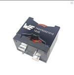
Or buy the premade Wurth super inductor. That’s super heavy gauge and looks cool.
I modified the pcb for mosfet version
Thank you x
Attachments
Not sure I follow you, the FH9/FH9HVX has always been designed for TO-247 style V-MOSFETs. The layout above looks very similar to the FH9 layout done years ago by S.K. Kachhap (Sonal K):
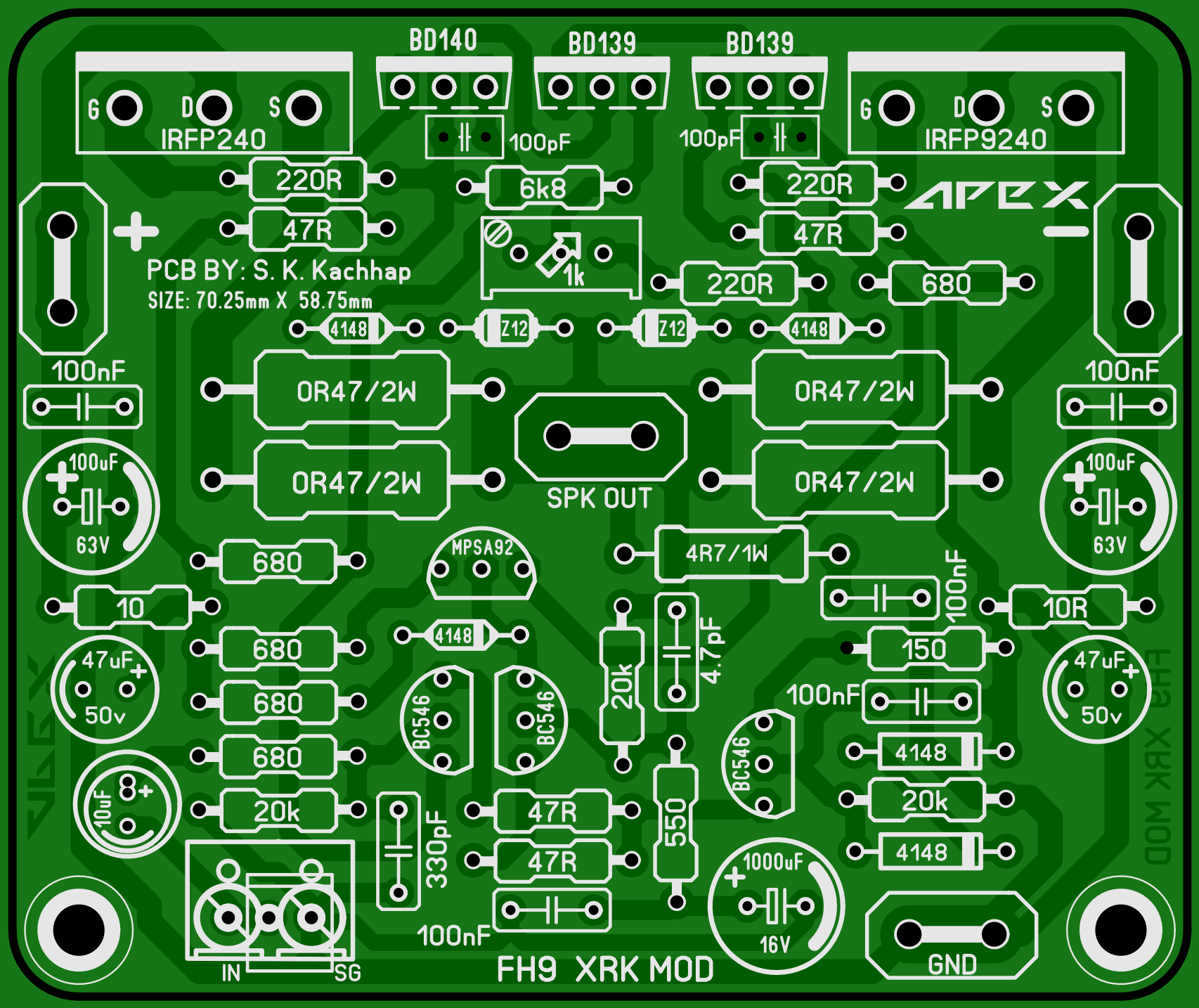
The current layout of the FH9HVX by JPS64 provides added benefits of via-stitched low impedance double traces on both sides for high current paths, optional external flying leads MOSFETs, and a spot for a Thiele output inductor, among other things.
The current layout of the FH9HVX by JPS64 provides added benefits of via-stitched low impedance double traces on both sides for high current paths, optional external flying leads MOSFETs, and a spot for a Thiele output inductor, among other things.
Last edited:
Hi Coolet,is it gauge 18? 1.2mm in metric?
I modified the pcb for mosfet version
Thank you x
just check your signal ground connection. I think it should be like
1. all signal gnd/FB gnd tied together
2. a 10ohm resistor then connects this signal gnd to pwr gnd.
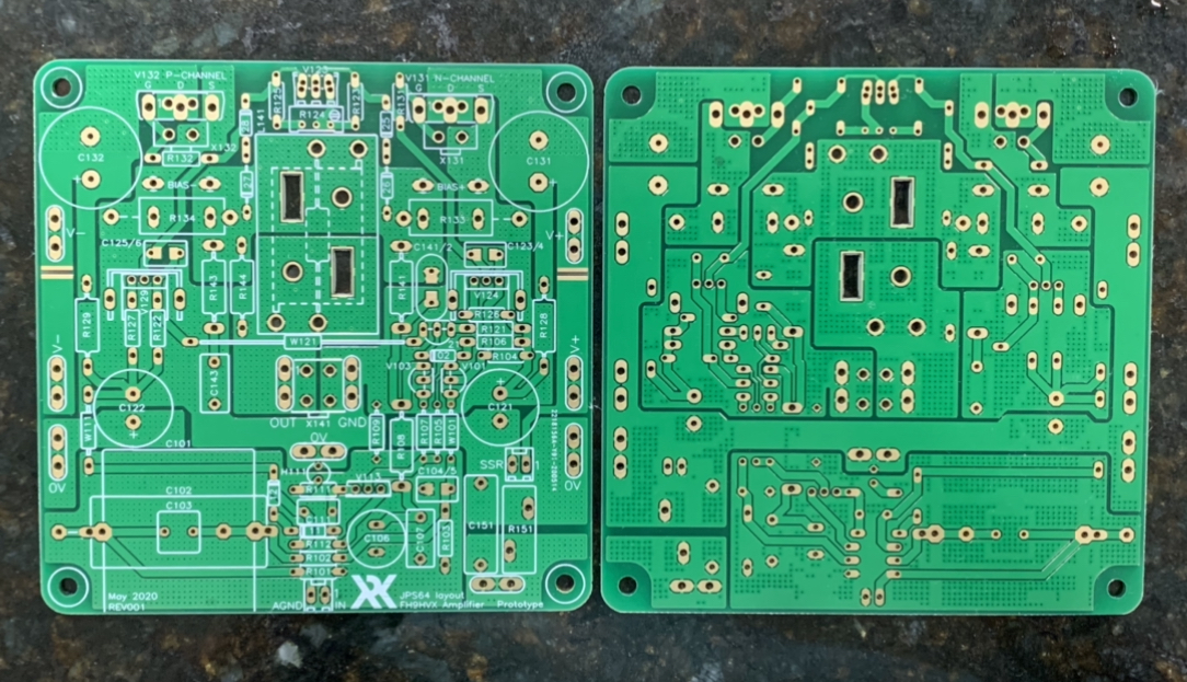
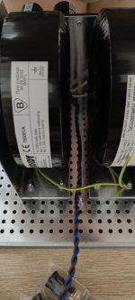
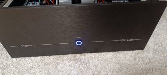
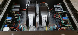
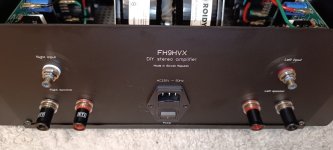
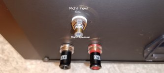
Friends, the front panel mounted, ...gave me a hard time as there is very little space. So far I am at a weight of 17,5 kg it will be a very massive companion.
I have yet to plug in PE. Just connect only the power supply to PE, or even the amplifiers themselves.
Thank You!
I have yet to plug in PE. Just connect only the power supply to PE, or even the amplifiers themselves.
Thank You!
Attachments

I like the sound very much, dynamics throughout the spectrum, ...mids and highs nice. Today I tested different genres on Amazon Music, I have nothing to complain about. The performance mosfets need to warm up a bit, about 200hrs and then it will have the right oomph.
PS: I compared with Audiolab 6000A, in a blind test I would probably miss which set plays
DC Offset: L (3mV), P (6mV)
Bias: 250mA
Hum: none is not heard, very weak noise heard only with the ear attached to the tweeter
PRIO: do the HPA-1 fitted with 4 pairs of furutech, and then I'm going to DIY the SB12.3 from ZaphAudio
Attachments
-
 IMG_20230911_195741.jpg405.2 KB · Views: 113
 -
 IMG_20230911_195757.jpg117.3 KB · Views: 114
 -
 IMG_20230911_195805.jpg185.3 KB · Views: 107
 -
 IMG_20230911_195815.jpg296.6 KB · Views: 112
 -
 IMG_20230911_195824.jpg184.6 KB · Views: 120
 -
 IMG_20230911_195831.jpg224.2 KB · Views: 107
 -
 IMG_20230911_195849.jpg148.4 KB · Views: 105
 -
 IMG_20230911_195905.jpg282.9 KB · Views: 107
 -
 IMG_20230911_195919.jpg244.9 KB · Views: 106
 -
 IMG_20230911_195945.jpg259.9 KB · Views: 103
 -
 IMG_20230911_200102.jpg285.1 KB · Views: 112
 -
 IMG_20230911_200111.jpg266.6 KB · Views: 114
 -
 IMG_20230911_200125.jpg217.9 KB · Views: 112
@xrk971
I had a question, have you tried to compare the sound difference of FH9HVX+Wurth coil on the core vs FH9HVX+air coil.
I am toying with the idea of making one more pair of FH9HVX boards with 1.5mm air coil with IXYS mosfets IXTH80N20L and IXTH48P20P. But I'm not sure if this investment makes up for the minimal improvement in sound.
The difference in sound is probably hard to tell. I have not made one with air core so cannot comment. But the air core would have to use really thick wire to achieve 98A current capability. Not that we need that much - just means you are operating well in the linear range of the inductor.
The larger IXYS may not sound as good because the gate capacitance is larger - it may not sound as snappy. It really wasn’t designed for that MOSFET in mind so you may need to adjust the small silver mica caps.
Those IXYS are great but the amp has not been proven with them yet.
The larger IXYS may not sound as good because the gate capacitance is larger - it may not sound as snappy. It really wasn’t designed for that MOSFET in mind so you may need to adjust the small silver mica caps.
Those IXYS are great but the amp has not been proven with them yet.
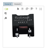
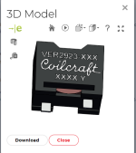
Coilcraft inductors don't work with this board.
Ask me how I figured it out.
I never used flat wire inductors before, and I was sure Coilcraft and Würth Elektronik coils will have the same footprint. I wonder why you didn't design this board to accept both of these brands.
Maybe next batch?
Ask me how I figured it out.
I never used flat wire inductors before, and I was sure Coilcraft and Würth Elektronik coils will have the same footprint. I wonder why you didn't design this board to accept both of these brands.
Maybe next batch?
Attachments
I did a little rewiring of my entertainment center yesterday, cleaned things up and removed a Behringer HD400 that I can't remember why I had in place initially.
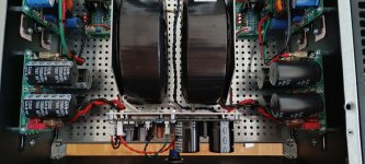
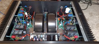
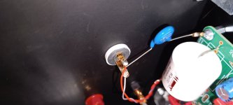
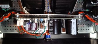
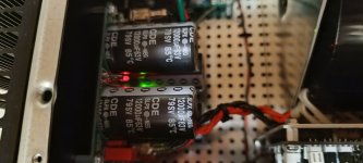
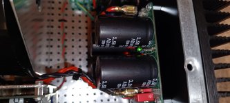
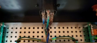
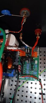
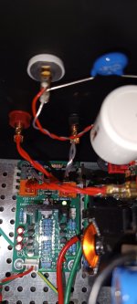
It turns out that my FH9HVX does have hum, and I am not really sure where to go in resolving it. I am hoping that some of the people here have some ideas or see something that I am not. Attached pics of my build as well as a block diagram. Listed out some initial troubleshooting, but not really sure what is next.


It turns out that my FH9HVX does have hum, and I am not really sure where to go in resolving it. I am hoping that some of the people here have some ideas or see something that I am not. Attached pics of my build as well as a block diagram. Listed out some initial troubleshooting, but not really sure what is next.
- Inputs shorted - no hum
- Inputs connected to each other - minor hum
- Any source (includes battery powered devices such as laptop or phone) connected without line transformers - hum
- Added 22R in series with RCA shield - no change to hum
You look like you have done everything correct.
Try connecting the rca panel feed through jack GND left and right to each other.
Next, try disconnecting ground from one of the RCA jacks.
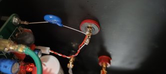
You might be missing the 0v GND between amp and PSU. You have PE from amp to chassis PE and PSU PE to chassis PE but that’s dirty GND. You need a clean GND from PSU to Amp - that gives RCA a low impedance common signal GND. Look at purple trace sketched below:

Try connecting the rca panel feed through jack GND left and right to each other.
Next, try disconnecting ground from one of the RCA jacks.
You might be missing the 0v GND between amp and PSU. You have PE from amp to chassis PE and PSU PE to chassis PE but that’s dirty GND. You need a clean GND from PSU to Amp - that gives RCA a low impedance common signal GND. Look at purple trace sketched below:
Thanks X, I will try the RCA changes and report back.
I do have the amp connected to PSU with the 0v ground, but it's maybe 16awg, I can't recall the gauge. Would that suffice or should I increase the 0v to something like 12awg? I color coded your etsy shop pictures of amp and all cee's with my connection points. Red for positive, black for negative, white for 0v. Let me know if I connected them incorrectly or if I should increase gauge of 0v.


I do have the amp connected to PSU with the 0v ground, but it's maybe 16awg, I can't recall the gauge. Would that suffice or should I increase the 0v to something like 12awg? I color coded your etsy shop pictures of amp and all cee's with my connection points. Red for positive, black for negative, white for 0v. Let me know if I connected them incorrectly or if I should increase gauge of 0v.
BH,
I believe you do have psu gnd connected to the amp board.
Try disconnecting green amp board PE gnd wire from both channels. You already have a GLB connected from the psu boards to star chassis gnd.
Edit, no need for wire that thick, 16ga is fine. You don’t have an arc welder there
I believe you do have psu gnd connected to the amp board.
Try disconnecting green amp board PE gnd wire from both channels. You already have a GLB connected from the psu boards to star chassis gnd.
Edit, no need for wire that thick, 16ga is fine. You don’t have an arc welder there
- Home
- Group Buys
- FH9HVX - Budget Conscious 100w Class AB for Lean Times