FH3-inspired Foam Core Mini Build HOWTO
I've gotten some requests to provide details of how to build the FH3-inspired mini speaker in foam core and thought that a new thread with the "how to" might be useful.
If you have been following the Foam Core or Cornu Spiral threads (http://www.diyaudio.com/forums/full-range/223313-foam-core-board-speaker-enclosures.html and http://www.diyaudio.com/forums/full-range/225622-ever-think-building-cornu-spiral-horn-now-you-can.html), this will be familiar. I recently built a smaller all foam core speaker inspired by the very elegant FH3 to see what it sounds like without having to cut any wood or having to invest too much time in the shop (if I had one). Being made of foam core boards from the dollar store, the maximum dimension would be 30 inches. I also wanted to use a smaller less expensive driver to match the smaller cabinet and to save money. Having my favorite budget Vifa TC9FD driver (Vifa TC9FD-18-08 3-1/2" Full Range Paper Cone Woofer 264-1062) on hand, I set out to design the new mini FH3-inspired speaker by scaling the cross sectional areas of the speaker's horn as a function of the driver piston area Sd. My calculations showed that the FH3 has nominal cross sections of 2x Sd at the folding point, 4x Sd at the base, and 1.06 x Sd at the terminus choke point. These were calculated from the published dimensions of the FH3 (http://www.google.com/url?sa=t&rct=j&q=frugel%20horn%20mk3%20plans&source=web&cd=9&cad=rja&ved=0CGMQFjAI&url=http%3A%2F%2Fwww.p10hifi.net%2FFH%2Fdownloads%2Ffrugel-hornMk3-1v0-250212.pdf&ei=h8TuUNO5K4W80QGh2YD4AQ&usg=AFQjCNFRzgZK1QjpBt2V3mP5wK3U97zfUw&bvm=bv.1357700187,d.dmg)and one of the recommended drivers - the MA CHR70. Armed with this knowledge and constrained by a maximum height of 30 inches, and knowing that the cabinet needs to be at least 4.5 in wide for the baffle to properly mount the Vifa, it was a simple matter to derive the cross sections at the fold point, the base, and the terminus for the Vifa driver.
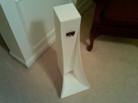
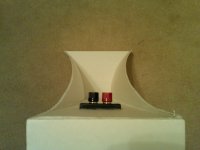
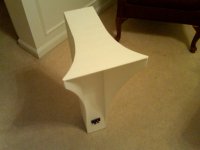
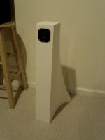
The resulting principal dimensions that came out of the scaling were surprisingly even and simple: 2.5 inches x 2.5 inches x 2.5 inches at the fold point for a base depth of 5.0 inches, and a terminus gap height of 1.33 inches. The cabinet is sloped back at an approximate 5 deg angle to form a parallelogram when viewed from the side. Rather than deal with angles, I measured a setback of 2.5 inches from vertical to approximate the angle. Thus will also require the height of cabinet (vertical) to be only 29.9 inches in order to preserve the 30 in length for the baffle. So we now have a very slender looking cabinet that is 4.5 in wide x 5.0 deep x 29.9 in tall. Such a cabinet would not be very stable and tip over easily requiring outrigger feet for stability. Foam core construction permits the neat ability to make compound or complex curved walls at will. Thus I decided to curve the rear horn walls outwards to give the base stability and provide more expansion for the rear facing horn mouth. So I expanded the rear mouth from 4.5 in to 12 inches over a distance of 10 inches.
Before actually putting razor to foam, I simulated the response in HornResp just to make sure the bass output was reasonable and to see where the tuning frequency was. It looked ok, with a main low bass peak at about 70 Hz and a dip around the 125 Hz region which is OK because that is the Fs of the Vifa and there should be enough output from the driver to fill in. diyAudio
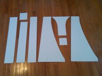
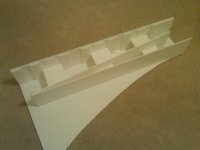
The build went very smoothly, one just has to use a good straight edge (I used a masonite panel) and a sharp razor. Make sure you account for the thickness of the board (3/16 in) as the dimensions above are internal dimensions. Draw the plan on one of the sides and begin by hot melt gluing the back panel. Use a square piece of foam core as a gage to ensure 90 deg angle while the glue sets. Then glue on the internal angled divider. Also use the 90 deg gage to ensure squareness. It helps to glue in sections at a time as 30 inches is too long of a stretch to do in a single stroke with hot melt. Then glue the front baffle, which I made wide to cover the front joints. It is trickier than the back or divider to glue as it is not lying directly on top of side. You can make construction easier by gluing it on the side just like the back if you make the sides deeper by 3/16 in to accommodate the thickness. Then bracing needs to be added, I had 3 major brace locations. These are cut to fit and jammed in place with hot melt taking care not to distort the squareness of the cabinet. I also added some front brace strips to serve as ledges for the final side to be glued on. I also added a second 4.5 x 4.5 in piece of foam behind driver for a double layer to give more support for the driver mounting.
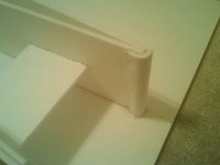
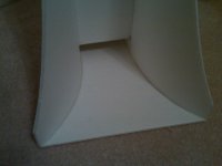
Then a curved piece needs to be glued over the terminus to provide a smooth flow at the mouth. Curves are made by scoring lines deep enough just to pierce the paper on the concave side to allow the foam to compress when you bend it.
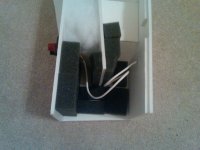
Next comes mounting the binding posts and adding wire to receive the driver once it is all buttoned up. I hot melted the binding posts onto the back and added crimped wire connectors with wiring for the drivers.
Now comes the dampening plan, I used the suggestions from the FH3 plans and added pillow stuffing into the closed end and used open cell foam to line the walls adjacent to the driver, ideally felt should be used. The top is left off for adjusting stuffing after build is complete. Now the second side panel is glued on with pva glue and a combination of hot melt at stragegic points to act as a tack while pva dries. I used books and dumbbells to clamp the side. Rubber bands can also be used to apply tension to clamp baffle edge to side as side is not on top of baffle.
Once the side gluing is complete, check for any leaks or gaps and fill in with more pva or run hot melt glue over gap to seal. Now the base is glued on with hot melt. Do the straight sections where the main box is first, then glue the curved sections in bits at a time while bending the horn mouth outwards like a wing. Hold in place with your hand while hot melt glue sets. It makes a nice graceful curve which now doubles as support feet.
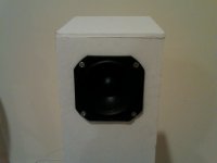
Finally, cut the hole for the driver - use a template and center it at 2.5 inches down from the top. Glue small strips of wood where the screws go to provide purchase for the wood screw threads. Install the driver and now add stuffing to cavity behind driver and maybe 2 inches below driver but no more as that will kill bass extension. Use a temporary means to fasten top on and listen to speaker, and adjust stuffing as needed to taste. I used quite a dense pack behind driver to absorb reflections that could go back out the cone. Once you are satisfied with sound, hot melt glue the top on and you are done.
How does it sound? Fantastic! There is plenty of warm deep punchy bass emanating from the terminus. The Vifa does a great job with the mids and highs. The sound stage and imaging are superb. The sound stage does not feel as wide as the Cornu but that is to be expected as it is not 24 or 28 inches wide. I like how the bass and mid bass sound more balanced than Cornu, but overall, the Cornu's wide sound stage and impressive mid bass still manages to knock my socks off. The foam core FH3-inspired speaker definitely is one of my favorites and I understand its popularity: not only does it sound great, it looks really nice. I like how it sounds so much that I started on the build of the second channel and promptly ordered more Vifa drivers as I am borrowing the ones from the Cornu spiral.
Each speaker uses about 3.5 sheets of foam core board. The total cost of each speaker is under $20 including driver, binding posts, foam core, and glue. The build time (not including glue drying time) is about 3 hours per speaker. The second one goes faster due to the learning curve.
Give it a try, it is a lot of fun, they sound great, and look even better.
these designs are NOT in any way approved, endorsed, or connected to the real frugal-horn.com Frugel-Horn designed/developed by Scott Dave, Chris.
I've gotten some requests to provide details of how to build the FH3-inspired mini speaker in foam core and thought that a new thread with the "how to" might be useful.
If you have been following the Foam Core or Cornu Spiral threads (http://www.diyaudio.com/forums/full-range/223313-foam-core-board-speaker-enclosures.html and http://www.diyaudio.com/forums/full-range/225622-ever-think-building-cornu-spiral-horn-now-you-can.html), this will be familiar. I recently built a smaller all foam core speaker inspired by the very elegant FH3 to see what it sounds like without having to cut any wood or having to invest too much time in the shop (if I had one). Being made of foam core boards from the dollar store, the maximum dimension would be 30 inches. I also wanted to use a smaller less expensive driver to match the smaller cabinet and to save money. Having my favorite budget Vifa TC9FD driver (Vifa TC9FD-18-08 3-1/2" Full Range Paper Cone Woofer 264-1062) on hand, I set out to design the new mini FH3-inspired speaker by scaling the cross sectional areas of the speaker's horn as a function of the driver piston area Sd. My calculations showed that the FH3 has nominal cross sections of 2x Sd at the folding point, 4x Sd at the base, and 1.06 x Sd at the terminus choke point. These were calculated from the published dimensions of the FH3 (http://www.google.com/url?sa=t&rct=j&q=frugel%20horn%20mk3%20plans&source=web&cd=9&cad=rja&ved=0CGMQFjAI&url=http%3A%2F%2Fwww.p10hifi.net%2FFH%2Fdownloads%2Ffrugel-hornMk3-1v0-250212.pdf&ei=h8TuUNO5K4W80QGh2YD4AQ&usg=AFQjCNFRzgZK1QjpBt2V3mP5wK3U97zfUw&bvm=bv.1357700187,d.dmg)and one of the recommended drivers - the MA CHR70. Armed with this knowledge and constrained by a maximum height of 30 inches, and knowing that the cabinet needs to be at least 4.5 in wide for the baffle to properly mount the Vifa, it was a simple matter to derive the cross sections at the fold point, the base, and the terminus for the Vifa driver.
The resulting principal dimensions that came out of the scaling were surprisingly even and simple: 2.5 inches x 2.5 inches x 2.5 inches at the fold point for a base depth of 5.0 inches, and a terminus gap height of 1.33 inches. The cabinet is sloped back at an approximate 5 deg angle to form a parallelogram when viewed from the side. Rather than deal with angles, I measured a setback of 2.5 inches from vertical to approximate the angle. Thus will also require the height of cabinet (vertical) to be only 29.9 inches in order to preserve the 30 in length for the baffle. So we now have a very slender looking cabinet that is 4.5 in wide x 5.0 deep x 29.9 in tall. Such a cabinet would not be very stable and tip over easily requiring outrigger feet for stability. Foam core construction permits the neat ability to make compound or complex curved walls at will. Thus I decided to curve the rear horn walls outwards to give the base stability and provide more expansion for the rear facing horn mouth. So I expanded the rear mouth from 4.5 in to 12 inches over a distance of 10 inches.
Before actually putting razor to foam, I simulated the response in HornResp just to make sure the bass output was reasonable and to see where the tuning frequency was. It looked ok, with a main low bass peak at about 70 Hz and a dip around the 125 Hz region which is OK because that is the Fs of the Vifa and there should be enough output from the driver to fill in. diyAudio
The build went very smoothly, one just has to use a good straight edge (I used a masonite panel) and a sharp razor. Make sure you account for the thickness of the board (3/16 in) as the dimensions above are internal dimensions. Draw the plan on one of the sides and begin by hot melt gluing the back panel. Use a square piece of foam core as a gage to ensure 90 deg angle while the glue sets. Then glue on the internal angled divider. Also use the 90 deg gage to ensure squareness. It helps to glue in sections at a time as 30 inches is too long of a stretch to do in a single stroke with hot melt. Then glue the front baffle, which I made wide to cover the front joints. It is trickier than the back or divider to glue as it is not lying directly on top of side. You can make construction easier by gluing it on the side just like the back if you make the sides deeper by 3/16 in to accommodate the thickness. Then bracing needs to be added, I had 3 major brace locations. These are cut to fit and jammed in place with hot melt taking care not to distort the squareness of the cabinet. I also added some front brace strips to serve as ledges for the final side to be glued on. I also added a second 4.5 x 4.5 in piece of foam behind driver for a double layer to give more support for the driver mounting.
Then a curved piece needs to be glued over the terminus to provide a smooth flow at the mouth. Curves are made by scoring lines deep enough just to pierce the paper on the concave side to allow the foam to compress when you bend it.
Next comes mounting the binding posts and adding wire to receive the driver once it is all buttoned up. I hot melted the binding posts onto the back and added crimped wire connectors with wiring for the drivers.
Now comes the dampening plan, I used the suggestions from the FH3 plans and added pillow stuffing into the closed end and used open cell foam to line the walls adjacent to the driver, ideally felt should be used. The top is left off for adjusting stuffing after build is complete. Now the second side panel is glued on with pva glue and a combination of hot melt at stragegic points to act as a tack while pva dries. I used books and dumbbells to clamp the side. Rubber bands can also be used to apply tension to clamp baffle edge to side as side is not on top of baffle.
Once the side gluing is complete, check for any leaks or gaps and fill in with more pva or run hot melt glue over gap to seal. Now the base is glued on with hot melt. Do the straight sections where the main box is first, then glue the curved sections in bits at a time while bending the horn mouth outwards like a wing. Hold in place with your hand while hot melt glue sets. It makes a nice graceful curve which now doubles as support feet.
Finally, cut the hole for the driver - use a template and center it at 2.5 inches down from the top. Glue small strips of wood where the screws go to provide purchase for the wood screw threads. Install the driver and now add stuffing to cavity behind driver and maybe 2 inches below driver but no more as that will kill bass extension. Use a temporary means to fasten top on and listen to speaker, and adjust stuffing as needed to taste. I used quite a dense pack behind driver to absorb reflections that could go back out the cone. Once you are satisfied with sound, hot melt glue the top on and you are done.
How does it sound? Fantastic! There is plenty of warm deep punchy bass emanating from the terminus. The Vifa does a great job with the mids and highs. The sound stage and imaging are superb. The sound stage does not feel as wide as the Cornu but that is to be expected as it is not 24 or 28 inches wide. I like how the bass and mid bass sound more balanced than Cornu, but overall, the Cornu's wide sound stage and impressive mid bass still manages to knock my socks off. The foam core FH3-inspired speaker definitely is one of my favorites and I understand its popularity: not only does it sound great, it looks really nice. I like how it sounds so much that I started on the build of the second channel and promptly ordered more Vifa drivers as I am borrowing the ones from the Cornu spiral.
Each speaker uses about 3.5 sheets of foam core board. The total cost of each speaker is under $20 including driver, binding posts, foam core, and glue. The build time (not including glue drying time) is about 3 hours per speaker. The second one goes faster due to the learning curve.
Give it a try, it is a lot of fun, they sound great, and look even better.
these designs are NOT in any way approved, endorsed, or connected to the real frugal-horn.com Frugel-Horn designed/developed by Scott Dave, Chris.
Attachments
-
 Foam-FH3-layout-960557547.jpg115.4 KB · Views: 3,902
 -
 Foam-FH3-build-bracing1670431727.jpg125.9 KB · Views: 3,817
 -
 Foam-FH3-damping11648466299.jpg155.7 KB · Views: 3,795
 -
 Foam-FH3-terminus-detail-1141689260.jpg98.4 KB · Views: 3,752
 -
 Foam-FH3-build-09-1067673785.jpg130 KB · Views: 3,967
 -
 Foam-FH3-build-11-1712313160.jpg126.3 KB · Views: 1,129
 -
 Foam-FH3-build-101105487053.jpg99.6 KB · Views: 896
 -
 Foam-FH3-build-12803233267.jpg126.9 KB · Views: 1,004
 -
 Foam-FH3-build-finished2-779268845.jpg91.9 KB · Views: 1,064
 -
 Foam-FH3-build-finished4-222524412.jpg133.5 KB · Views: 1,284
Last edited:
Just to point out, FH3's expansion is not derived from driver piston area, so scaling it based on the Sd of the drive unit is not likely to result in a similarly scaled alignment. I haven't done a box for 3in units because I don't like tuning drivers so far below Fs, even in a full sized 'optimal' horn; harmonic distortion rockets.
Last edited:
That's Great! Seriously easy builds sans having to deal with cutting ply
Kinda questions the All panels must Dead rules tho.
$ store foam is the crappiest quality foam core board on the planet (don't let it get moist/damp !) genuinely Cheap though. Elmers' from Michaels' is far better but it's 2$ a sheet and best quality is Bienfang from an artists store.
Far pricier and perhaps overkill.
Then there is Gator Board up to 1" thick and plastic/glass skinned
Kinda questions the All panels must Dead rules tho.
$ store foam is the crappiest quality foam core board on the planet (don't let it get moist/damp !) genuinely Cheap though. Elmers' from Michaels' is far better but it's 2$ a sheet and best quality is Bienfang from an artists store.
Far pricier and perhaps overkill.
Then there is Gator Board
up to 1" thick and plastic/glass skinned
Last edited:
Just to point out, FH3's expansion is not derived from driver piston area, so scaling it based on the Sd of the drive unit is not likely to result in a similarly scaled alignment. I haven't done a box for 3in units because I don't like tuning drivers so far below Fs, even in a full sized 'optimal' horn; harmonic distortion rockets.
Scottmoose,
Good point and you are probably right about this not being an optimally scaled alignment. I really had nothing else to go on and wanted to keep it looking as similar as possible. Is the process of finding the optimum expansion to use the simulation and try different ones? Or do you use guidelines or 'golden' rules first then tweak via simulation?
That's Great! Seriously easy builds sans having to deal with cutting ply
Kinda questions the All panels must Dead rules tho.
$ store foam is the crappiest quality foam core board on the planet (don't let it get moist/damp !) genuinely Cheap though. Elmers' from Michaels' is far better but it's 2$ a sheet and best quality is Bienfang from an artists store.
Far pricier and perhaps overkill.
Then there is Gator Board
I have some of the Elmer's board and you are right, the quality of the paper is much better but it's almost too thick to cut easily and the foam actually has glass fibers interspersed for strength so the foam doesn't cut neatly but gets ragged edges. It might be ideal if you had a simple straight shape like the front or back, but for complex curves, or if you wanted to score it for curving or bending it, the cheap dollar store stuff works best. The next step is to decorate the cheap foam core with fabric/wall paper/ etc. that should add some strength and make it not look so sterile. Thanks for the suggestions.
Scottmoose,
Good point and you are probably right about this not being an optimally scaled alignment. I really had nothing else to go on and wanted to keep it looking as similar as possible. Is the process of finding the optimum expansion to use the simulation and try different ones? Or do you use guidelines or 'golden' rules first then tweak via simulation?
Depends on the circumstances. I typically design a speaker to a given criteria / alignment, and then model it. If any obvious tweaks are possible, or it indicates I've made an almightly Horlicks of something somewhere along the line, then I'll adjust the design accordingly. After that, if called for, physical prototyping can be done.
Last edited:
Scottmoose,
OK, so if one were to design a horn of similar appearance to the FH3 for a 3 in to 3.5 in driver, can you please explain the basics of the design process? It may be to select an appropriate driver to start with rather than designing around the cheapest driver you have on hand
Thanks,
Xrk971
OK, so if one were to design a horn of similar appearance to the FH3 for a 3 in to 3.5 in driver, can you please explain the basics of the design process? It may be to select an appropriate driver to start with rather than designing around the cheapest driver you have on hand
Thanks,
Xrk971
can you please explain the basics of the design process?
10 years of experience and some proprietary design tools.
dave
I understand the reluctance to give away one's hard-earned craft developed over 10 years...
I guess I will have to rely on MJK's papers:
Horn Theory
and some of the resources that George (@gpapag) gave on the Dinsdale papers:
http://www.metaleater.narod.ru/Dinsdale_Horns_1.pdf
http://www.metaleater.narod.ru/Dinsdale_Horns_2.pdf
http://www.metaleater.narod.ru/Dinsdale_Horns_3.pdf
I guess I will have to rely on MJK's papers:
Horn Theory
and some of the resources that George (@gpapag) gave on the Dinsdale papers:
http://www.metaleater.narod.ru/Dinsdale_Horns_1.pdf
http://www.metaleater.narod.ru/Dinsdale_Horns_2.pdf
http://www.metaleater.narod.ru/Dinsdale_Horns_3.pdf
That helps.
I'm hardly an authority on horn design though, unlike some people here who've forgotten more than I'm ever likely to know. However, FWIW, from my POV, while the Vifa is a good driver for what it is, it's not all that ideal for horn loading. You can, but the useable horn-loaded BW is really only between 83Hz - 188Hz. More to the point, as I mentioned, I haven't done a box for this size driver because I don't regard the tradeoffs to be acceptable. 3in - 3 1/2in units are big tweeters & IMO if you run them sans filters, then they are best sealed or aperiodic (or at least what is often called aperiodic) unless you can go to a full-size horn with digital delay of course. Even then, most of the time you're accepting a goodly dose of HD. These things are all relative of course, but I've put my cutoff at 4in drivers on that score, and I try not to tune too low with those either. Advantages & disadvantages to that too; nothing is entirely black & white, but you've got to accept some compromises or you'd never do anything at all.
Edit:
There are vast numbers of papers and books available on horns or on the physics related to them. Dinsdale has errors, but it's a good general start / background. Martin's are as good as you'd expect from the source (very good). After that, you've got papers by Keele and Leach who took most of the fun out of horn design in the '70s, and then you can go even further with the large number of AES and ASA papers presented / published on various aspects of the subject, books by Beranak, Olson and Rayleigh who cover related matters, university thesis, texts on the physics of musical instuments etc. After that, you can move away from audio / music related fields into related engineering matters. Depends how far you want to go.
Last edited:
That helps.
I'm hardly an authority on horn design though
Au contraire...
and some of the resources that George (@gpapag) gave on the Dinsdale papers:
Note that althou a very good basis, Dinsdale's papers have some holes in them.
dave
PS: when i did those scans 10+ years ago i never expected them to spread so far.
Note that althou a very good basis, Dinsdale's papers have some holes in them.
far.
What might the holes or errors in the Dinsdale papers be?
I'm hardly an authority on horn design though, unlike some people here who've forgotten more than I'm ever likely to know. However, FWIW, from my POV, while the Vifa is a good driver for what it is, it's not all that ideal for horn loading. You can, but the useable horn-loaded BW is really only between 83Hz - 188Hz.
Ok, if I want to try a relatively low cost driver that is in the 4 in range that is more suitable for horn loading, which would you recommend? A CHR70? Or an FF105wk? What about a Fountek FE85 which although is only a 3 incher has a similar cutout to the Vifa and is about the same price?
Last edited:
Update: Stereo Finally
My order of Vifa drivers arrived today and I finished the final assembly and adjustment of stuffing in the second foam core horn. I put in my test CD's, put the FH3-inspired foam core horns about 3 ft from the wall and 7 ft apart with a little toe-in, put a chair about 10 ft away, sat down and listened...
So here are my impressions of these foam speakers: Wow! They sound really good! As expected, they excel at jazz, vocals, and pop. I tried some rock and they are pretty good there too - there is some surprising bass from a tiny 3.5 in driver. The spatial imaging is superb, I could pick out each instrument and its location on the stage. And there was something new and unexpected: I could hear something that I never heard before on a certain track that I listened to all the time. It was the sound of the brush of the drummers hand against the rim of the drum as he was swishing the stick around on the drum head. Pretty cool stuff. Anyhow, the detail that these Vifa's have still manages to surprise me. I will have to listen some more as I have not had a chance to crank it up loud as everyone is asleep, but so far, this build has exceeded my expectations.
My order of Vifa drivers arrived today and I finished the final assembly and adjustment of stuffing in the second foam core horn. I put in my test CD's, put the FH3-inspired foam core horns about 3 ft from the wall and 7 ft apart with a little toe-in, put a chair about 10 ft away, sat down and listened...
So here are my impressions of these foam speakers: Wow!
They sound really good! As expected, they excel at jazz, vocals, and pop. I tried some rock and they are pretty good there too - there is some surprising bass from a tiny 3.5 in driver. The spatial imaging is superb, I could pick out each instrument and its location on the stage. And there was something new and unexpected: I could hear something that I never heard before on a certain track that I listened to all the time. It was the sound of the brush of the drummers hand against the rim of the drum as he was swishing the stick around on the drum head. Pretty cool stuff. Anyhow, the detail that these Vifa's have still manages to surprise me. I will have to listen some more as I have not had a chance to crank it up loud as everyone is asleep, but so far, this build has exceeded my expectations.- Home
- Loudspeakers
- Full Range
- FH3-inspired Foam Core Mini Build