Progress
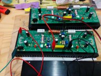
...So I may have gotten a little impatient. I ducked down to the local electronics store and grabbed some ceramics in the appropriate values to finish the build. So she's powered up and seems to be working fine!
Some caveats on it though. The fuses are random old uk power plug items rated to 3A - they're the only things on hand I had that fitted! I bunged in a bf862 instead of a k170 and didn't do anything to alter the bias of it at all - this'll need changed at some point. I've realised that with lower rail voltages on my build (+- 25V)I'll need to change a few other parts as well - notably R12 I suspect.
Otherwise, I'm looking forward to doing a trial run tomorrow and seeing how it sounds!
Attachments
Nice build,Im very curious about your findings of the bass.I could compair my FetZilla with a regular PSU and with SMPS like yours.I didn't use any extra cap like you did when I used the SMPS and it was bass shy compaired with a regular PSU.
I can't compare to anything except my old amp, the Musical Fidelity B1. As far as i can tell, the bass output is pretty much the same or ever so slightly less, but subjectively more defined/detailed. On some tracks i feel the bass may be a bit shy, but i will have to do a straight A/B comparison to be sure.
The Fetzy sounds subjectively "better" than the B1, in that it is a tad more lifelike. I'm holding out final judgement until the Fetzy has gone through a thorough burn-in session and until it is boxed up.
Even though i'm usually very much against this sort of thing, i made a video showing the setup in action. I seriously doubt anyone is able to gauge the bass output from it however.
The turn-on thump is fairly brutal however. Haven't turned it off yet so don't know what the turn-off sounds like, but i suspect it's definitely noticeable.
https://vimeo.com/92870211
Last edited:
...So I may have gotten a little impatient. I ducked down to the local electronics store and grabbed some ceramics in the appropriate values to finish the build. So she's powered up and seems to be working fine!
Some caveats on it though. The fuses are random old uk power plug items rated to 3A - they're the only things on hand I had that fitted! I bunged in a bf862 instead of a k170 and didn't do anything to alter the bias of it at all - this'll need changed at some point. I've realised that with lower rail voltages on my build (+- 25V)I'll need to change a few other parts as well - notably R12 I suspect.
Otherwise, I'm looking forward to doing a trial run tomorrow and seeing how it sounds!
Looks good, looking forward to hearing your impressions! I'm also waiting on some of those SOT23 adapter PCBs, slowly making their way here from China.
Have a feeling the BF862 dropped in instead of SK170 will sound subjectively better, and possibly even more so once we up the bias, can't wait to try it.I drew attention to this and my comment was rubbished.................The turn-on thump is fairly brutal however. Haven't turned it off yet so don't know what the turn-off sounds like, but i suspect it's definitely noticeable...........
Looks good, looking forward to hearing your impressions! I'm also waiting on some of those SOT23 adapter PCBs, slowly making their way here from China.
The BS170 seems to be a good replacement
I drew attention to this and my comment was rubbished.
Yeah, i think i saw that discussion. Well, i believe the thump can have some variance, and the way the SMPS300RE first waits, then slams on(versus a linear supply's slightly more gradual turn-on), could make the turn-on subjectively louder. Probably others who built the Fetzy and questioned your findings had either a linear supply, less sensitive speakers/ears, or both.
I rarely turn off my amp anyway(out of laziness) so i don't fret too much over this. The only thing slightly irking me is my MF B1 is completely void of any audible turn-on/turn-off noise, and this is without any relays, so its a bit of a downgrade in this respect. TdP does have some skills.
One thing that i think may have to do with grounding in my current ad-hoc setup, with the source connected but switched off there is complete silence, even with my ear right next to the tweeter. But source on and not playing, there is a HF-type irregular noise, but i'm holding out judgement until i have a proper grounding scheme.
Did your NFetzilla exhibit the same turn-on thump by the way?
Good Question, I can't remember................Did your NFetzilla exhibit the same turn-on thump by the way?
There is still a version of it on my parts' shelf.
Should hook it back up. I need to check for and compare AC output noise.
Yeah, i think i saw that discussion. Well, i believe the thump can have some variance, and the way the SMPS300RE first waits, then slams on(versus a linear supply's slightly more gradual turn-on), could make the turn-on subjectively louder. Probably others who built the Fetzy and questioned your findings had either a linear supply, less sensitive speakers/ears, or both.
I rarely turn off my amp anyway(out of laziness) so i don't fret too much over this. The only thing slightly irking me is my MF B1 is completely void of any audible turn-on/turn-off noise, and this is without any relays, so its a bit of a downgrade in this respect. TdP does have some skills.
One thing that i think may have to do with grounding in my current ad-hoc setup, with the source connected but switched off there is complete silence, even with my ear right next to the tweeter. But source on and not playing, there is a HF-type irregular noise, but i'm holding out judgement until i have a proper grounding scheme.
Did your NFetzilla exhibit the same turn-on thump by the way?
The designers of the FetZilla and Hugh have desided not to take away the turn on thump cause it had to much influence on the sound.You can read it at the older FetZilla threads.
Ok, after maybe 50-100 hours of play time, things are starting to stabilize. Seems my judgement about the amount of capacitance and the SMPS300RE was a tad premature. The very first power-on was fine, but the subsequent power-ons have yielded several turn-on thumps indicating the SMPS hits overload protection and cycles. So the soft-start is back in, and will definitely consider a speaker delay. Question is relay or solid-state? Maybe use the same time constant as the inrush current limiter and just activate two relays instead of one to save some complexity.
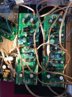
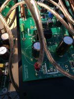
As promised here is my "special" C13/C14 arrangement. Before these caps were fitted there was perhaps a ever so slight edge to the treble. Could be placebo effect but the feeling is they definitely silkify the top end.
I did it like this because i wanted as short a run as possible between the output devices and the compensation caps, and the JB JFX were about as cheap as the MKT caps would've been. Please excuse the exceedingly crappy wiring.
Attachments
It's alive - and a bit of an impasse
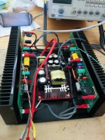
Hey all, I've mine up and running, but I've hit a bit of an impasse and as one of those who struggles with 'analysis paralysis' I feel a bit stuck! I'd appreciate a bit of input if anyone is keen to offer suggestions.
First up is the value of R12. With lower rails of +-25V and, say, 12mA as suggested bias through the VAS, I make it to be a voltage drop of 26.4 V across this resistor. This leaves 25V potential (versus 45V for normal rails) left for the remaining components to drop. I don't properly understand what purpose this resistor actually serves in this string (Or even if it's actually needed now!) other than to reduce dissipation across the two Fets in the vas string. I guess the question is what value should this resistor be in my situation.
Second is biasing the Jfet - I've a bf862 in there and whilst the transconductance numbers are equivalent to a k170GR it's about 3 times the Idss. A conversation in another thread with AKSA (Hugh) suggests that this part should be biased to about 2/3 of Idss, but in playing with the sim of the amp I can't get everything downstream from this part to 'balance' if I play with R8 and R10. And in fairness I don't know what I'm actually trying to achieve exactly! I have some k170's of a lower Idss on hand, but that feels a bit like giving up on learning something, and that's why I'm here. If anyone has any advice here, please let me know.
Thirdly is the turn on thump - my unit does this quite nastily, and it seems that this shouldn't be the case. There's a post from Paul Bysouth in one of the threads about what the turn on behavior should be... which I'm not seeing. I'm wondering about other solutions like a slow turn on (cap multiplier style) pass transistor on the rails after the SMPS, or a speaker delay/protection circuit and all that entails. Any thoughts?
Cheers all!
Edit - realised there's some oddities in my build I should explain. I jumpered the loop breaker in the end as I realised that the SMPS is earthed in two places to the chassis and I didn't want the NTC resistor in the loop back from the speaker to the PSU ground (which is at chassis ground). I'm a bit fuzzy on this logic, but I wasn't sure so this seemed a good idea for now. Wiring is untidy for now and I intend to tidy that up
Attachments
Last edited:
Hi AS,
Quick reply, thank you for your email.
#1 R12 is used to ensure that around Vcc - 10V is dropped. With 36V rails, it's dropping around 26V, so 2k2 is around 12mA. With Vcc of 25, I'd reduce it to 1K5, so that you are passing around 10mA (adjust T3 trimmer P3 so you have around 10V across it). Lower rails means lower power, and of course lower current is now possible to drive the gates.
#2 Changing the input jfet is fraught with problems. The 2SK170 was chosen to give Idss, transconductance, and noise. If you change to a device with an Idss of three times, it will be operating right outside the most linear region AND the input thump will be quite severe.
#3 Turn on thump is a perennial problem for all amplifiers. Most interpose a relay to disconnect the speaker until the offset has stabilised, but this approach may cost sonics and certainly considerably increases complexity. A complex amp is rarely built! There are issues we needed to consider..... The amp was optimised for 2SK170, ZVG, and lateral outputs all driven by 36V rails - any change, even slight from this implementation, will result in thumps, difficulties with output quiescent adjustment, and possibly sonics.
Conclusion: Try to get the correct input 2SK170 with Idss around 7mA. Consider a higher power supply voltage. Changes in the devices and voltage supply specified if effectively taking the amp back to square one for optimisation. At the BF682 and 25V rails you have lost the very elegant optimisation.
Sorry, probably not you wanted to hear. I cannot tell you have it sounds like you have it - but it won't be the same as the original operating points.
Cheers,
Hugh
re post 251
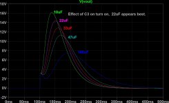
With a `standard' FETzilla (if such a thing exists), there will a turn on `thump'. The turn on behaviour is determined mainly by the values of C3 (22uF) and C7 (470uF) and to a lesser extent the values of C1, R3 and the jfet Idss and Vgs threshold.
Initially the output jumps up to about 1 volt, but due to its rise time and voltage, it isn't usually audible. Then the output slowly rises to about 8 volts. As this rise time is less than 10 Hz you will not hear it, but you will see the woofer cone move. During the development of the FETzilla, I ran hundreds of LTspice models to get the turn on behaviour to be acceptable, namely slow rise and fall times. Hence the C3, C7 values.
The attached images show my model of the turn on behaviour using a simple model for the power supply (ie 50Hz voltage source with a series resistance as determined by the transformer regulation, but without any inductance). This crude model shows an exaggerated `thump'. The other image shows the actual turn on behaviour as measured by Greg. Note the initial fast rise to about 2 volts, then a slower rise to about 9 volts.
With a SMPS, the power supply will turn on much faster than a toroid, so the response is more likely to be more like my model rather than Greg's actual response.
During this time, I was also interested in what a BF862 jfet would work like. I was never able to get a suitable turn on behaviour no matter what I tried (and I tried about 50 variations). A speaker relay is probably your only choice, or go back to a 2sk170 jfet.
More next replay,
Paul Bysouth
Attachments

FETzilla bootstrapped CCS
The FETzilla uses a bootstrapped constant current source (CCS) as the load on the Voltage Amplification Stage (VAS, ie T2), which has the benefits of both a bootstrapping and a CCS, and none of the disadvantages of either on their own. The bootstrap (ie C8 and R12) allows the CCS to be pulled lower than the negative power rail, and hence T5's gate can be pulled as low as necessary to get maximum negative output.
T3 is a small To92 sized DN2530 depletion mode mosfet, and its maximum dissipation is limited to about 100mW, hence if it is running at 10mA then the maximum voltage across T3 will be 10 volts. To get a DN2530 to operate as a constant current source, it needs to have at least 3 volts across the drain to source, and 5 volts is better. So aiming for 7 to 8 volts is about right.
This means that (with no input signal) R12 will need to drop the remaining voltage. The T3 drain will be at about -1v, about 2 volts across P3, and about 7 volts across T3 (total 10 volts), so R12 will need to be (36v - 10v) / 10mA) = 2.6Kohm, and for 12mA 2.1Kohms. Hence 2.2Kohms was specified. If you run the amplifier with 26 volt rails, then 1.5 Kohms is about right.
I run my FETzilla on 32 volt rails (R12 = 1.8Kohms). It works very well up to 30 watts (8 ohms), and then starts to struggle a bit (ie increased high order distortion harmonics) up to its limit of 50 watts. I think it works far better than it should for such a simple amplifier with just 5 active devices. There is a lot to be said for keeping amplifiers as simple as possible (but no simpler).
Paul Bysouth
And now to understand why!
Cheers guys. That's a good bit of info to digest on the build. I have to say I'm humbled you'd both take the time to chip in to give me a hand. Thank you kindly!
@Hugh - Gotcha - R12 down to 1K5, and the goal is to get the node at C8/R12/P3 to -10V at 10mA of bias. I believe I understand the reasoning around the K170 operating points as well, so I'll just swap out the BF's and drop in the K170's I have here. I'll quietly hope I'll have rectified the thump with this as well and leave off adding a speaker delay. Oh, and as for not what I wanted to hear; I'm here to learn stuff so your answer is music to my ears (sorry for the pun...)
@Paul. Thanks for the details! I think I see how the jfet gets to it's operating point over time and I'll have a play with the sim to understand the details of it (thanks again for the sim model!).
To query though, a higher Idss Jfet would speed up the time C7 takes to reach it's operating point (by allowing more current through initially), thus altering the output curve you've shown for startup. The Greg curve shows real life with a linear supply, however the SMPS will hit it's output voltage's quite quickly so the curve will be more like your sims.
So for the guys who've reported a turn on thump, the reality sits with the Jfets they have - higher in Idss than the preferred 5mA parts specified for fetzy.
As a way foward - I've K170's here (genuine? Maybe!) that I've measured at 7.8mA Idss. So I'd like to bias the jfet at 5mA lets say? (2/3 Idss as specified by Hugh). I do this by altering the value of R8 to, um, 750R? Assuming the idea is to maintain the operating point of the VAS.
...
I just did a bunch of sims, and the output gets very close to the limit of offset adjustment with R8 at 750R; perhaps 820R is the lower limit (at +-25V rails)?
Finally, my objective with the lower rails was potentially upping the output bias, and running in class A a bit more. I'll be pairing it with some high efficiency speakers so I'd the thought that I'd be spending most of my time in class A operation. Any obvious flaws in that plan?
Thank you again,
Aren.
the bias current through T1 jFET has to pass through R8 from the +ve and through R11 to the output Rail.................................. I've K170's here (genuine? Maybe!) that I've measured at 7.8mA Idss. So I'd like to bias the jfet at 5mA.......................
P2 is used to set output offset.
Starting from the assumption that output offset is exactly ZERO.
The 5mA you have decided on, must pass through R11 and drop 5V.
This places T1s @ +5.000Vdc
The gate must be slightly below this to allow that 5mA to flow. Expect the gate voltage to be around 4.500Vdc to 4.99Vdc.
If you are using 1k5 for R8, then that leaves T1d @ 25-[0.005*1500] = 17.5V
The Vds of T1 must therefore be 17.5 minus 5V, i.e. 12.5Vds. This is well within T1 capability. Pq ~ 0.005*12.5 ~ 63mW
Look up the datasheet for the k170 and find what Vgs is required for a 7.8mA Idss device to pass 5mA.
It's this voltage that P2 tries to secure to get the final output offset. ( I would need to look again at my NFetZilla, but I think I used three LEDs to get sufficient voltage to turn on T1. I did post a sch. If two LEDs gives a bias voltage of <4V then the current through R11 must be <4mA)
Why does all the T1 current flow through R8 & R11?
Because all the other routes are either DC blocked with capacitors or is a gate (which flows no current).
Last edited:
...
and that took a bit of thinking, but yes I do follow.
...
I need to think a bit more about what the Vgs on T2 achieves, given Vg on T2 is set by R8 essentially (given it sets bias for T1, and it's drop determines Vg for T2) and T2 Vs is determined by the T2 bias and R7.
So if i drop R8 to a lower value/higher bias I alter Vgs on T1 via P2 to achieve zero offset, but in doing so I alter Vgs on T2, which pulls Vd on T2 to wherever that is on the curve for that part. This in turn sets Vg for T4 and T5.
I'm going to read what I just wrote again a few times till it sticks
P3 sets the VAS bias current........determined by the T2 bias and R7........So if i drop R8 to a lower value/higher bias............. ...........
Look at the sch.
It states such.
Look at the string of devices from R7 to R12.
All the current that passes through R7 has to come out at R12.
All routes off to other parts of the circuit are DC blocked or a gate.
So P3 sets the VAS current.
Last edited:
Fwiw, i decided to implement 2 SSR's per channel, one across a fixed charging resistor(value TBD) and one in series with the speaker. This to allow me to go full capacitance and get rid of speaker thump. I use an SMPS, 36V rails, and a SK170 that i got from Patrick and instinctively have way more than 1V on turn on. The cones look to go a least out to Xmax, probably beyond. i've tried measuring the peak but don't own a scope.
My turn-off behaviour more closely resembles the one indicated by Paul, Hugh et al. Maybe it is because i used a Nichicon muse BP (as in bipolar) for the 470uF feedback shunt cap?
The TrenchFETs i bought were expensive, but feature a 5mOhm(@10V) spec, and i do believe i can get away with just using one bypassing the supply rail inrush limiting.
But it also got me thinking about protection, and i feel i want something to protect stuff in case the SMPS packs it in and decides to put out its full DC(which i believe can be several hundred volts). Maybe some kind of gas discharge crowbar protecting everything after the SMPS.
I'm going to live with my Fetzy for the forseeable future and want it as reliable and safe as the very best out there.
Ill post again when i have a finished and tested build for the safety circuits.
All Mains Powered SMPS have an isolating transformer that separates the Mains side from the user side................thinking about protection, and i feel i want something to protect stuff in case the SMPS packs it in and decides to put out its full DC(which i believe can be several hundred volts). Maybe some kind of gas discharge crowbar protecting everything after the SMPS............
That isolating transformer is what keeps you and I alive.
You should NEVER get Mains voltage on the output of an SMPS that meets standards.
Speaker protection is good for peace of mind. Go for it.
- Status
- This old topic is closed. If you want to reopen this topic, contact a moderator using the "Report Post" button.
- Home
- Group Buys
- FetZilla groupsbuy 5