During this time, I was also interested in what a BF862 jfet would work like. I was never able to get a suitable turn on behaviour no matter what I tried (and I tried about 50 variations). A speaker relay is probably your only choice, or go back to a 2sk170 jfet.
More next replay,
Paul Bysouth
Very interesting! Since i plan on having a speaker relay, i'm most interested in the variation(s) of this that a) gives highest fidelity and b) requires the least amount of component changes. Care to share/elaborate a little?
")
The first thing i thought i'd try is dropping a BF862 straight in instead of the SK170, but i'm very interested in increasing the current through this stage.
Thanks!
The Id will be less than Idss.
As Id gets lower, Vgs needs to go up, negatively.
If you start with a 7mA Idss k170 and bias it to 5mA then Vgs will be about -50mVdc.
If you want a lower current then Vgs will be higher, i.e. towards -100mVdc.
If you start with an 11mA Idss then the Vgs will need to be much higher to get down to a 5mA Id.
Use the datasheet to guide you to the required Vgs for your selected Id Vs Idss.
the bias current through T1 jFET has to pass through R8 from the +ve and through R11 to the output Rail.
Doesn't this also imply that as we decrease the value of R8(increasing current through T1, but also increasing the voltage seen at T1's drain?) we should also look at increasing the value of R11(so as to maintain the same current flowing to the output?)
AndrewT said:Use the datasheet to guide you to the required Vgs for your selected Id Vs Idss.
If i'm both understanding you correctly and reading the datasheet correctly(Fig. 7), i should shoot for something like -300mVdc Vgs to get around 8mA Id, assuming i have a ~12mA Idss BF862?
I can't seem to figure out however if this is within safe dissipation of a BF862(i guess <200mW). I guess i really need to figure out how to use LTspice to save everyone's time, although you folks have commendable patience in elucidating this for me!
Humbly,
Kris
Attachments
Last edited:
8mA Id and 12.5Vds amounts to 100mW of dissipation. Pmax is 300mW (nxp)
Pq << 300mW
You must de-rate the Pmax for the Tc achieved at the dissipation you end up with. I'd guess at <=30% of 300mW i.e. less than 100mW and preferably, for less thermal drifting, <50mW
100mW seems too much (to me) unless you have additional cooling on the sot23.
fig7 on the nxp datasheet shows ~150mVds for 8mA Id for ~12mA Idss.
The To92 device is using 5mA of Id @ 12.5Vds = 62.5mW. ~16% of 400mW
I would look at using ~4mA for a sot23 device and/or maybe lowering Vds to 8 to 10Vds instead of 12.5Vds.
A BF862 with an Idss of 6 to 8mA will operate well at 4mA to 5mA Id.
Last edited:
Hi, very clear and precise explanation, thanks you!
I think it looks like i definitely want to lower Vds then because i have a feeling my BF862's will turn out to have an Idss significantly higher than 8mA. On this forum a guy bought 200 BF862 from 2 factories, and they all had an Idss centered around 16mA:
http://www.diyaudio.com/forums/parts/229827-nxp-bf862-warning.html#post3366728
Let's say for argument's sake that i wish to drop Vds really low, say to 3 Volts(or cascode the BF862 a la JG filter buffer maybe?), so i can safely crank up the Id to get my 16 mA Idss jfets operating as linearly as possible without exceeding say 75mW dissipation(i.e running slightly hot), is this feasible with the current Fetzy T1 arrangement? Maybe when Paul comments on some of his BF862 variations he can shed some light on what he tried. Added complexity for me at this point is a good thing! A complex amp is rarely built as Hugh says, but when the commitment is there already, i welcome the complexity.
This is really intriguing, i have a feeling the amp with a correctly operated BF862 along with some re-optimisations is going to both look and sound slightly different, can't wait to find out which is preferred to my ears!
Last edited:
gm, conductance changes with Id.
If you reduce Id you reduce conductance.
That makes the open loop gain slightly lower and thus reduces the risk of instability.
If you increase Id you increase conductance.
That makes open loop gain slightly higher and thus increases the risk of instability.
If the existing set up has stability margins adjusted to specially suit a sk170 @ 5mA Id then any high conductance jFET run at 8mA may result in you having to establish the compensations to suit the increased Id.
A low conductance device run at high Id may not have this problem, but that is just a guess from an amateur that has never got a handle on compensation.
You can significantly reduce dissipation by adding a cascode.
The cascode can be a BJT or a jFET.
The jFET cascode is the simplest, but you would have find a device that would have a high cascode voltage at 8mA. Try for Vgs ~ >= Vp of the sk170/bf862. A BF245C will probably not manage that. Just solder the jFET cascode to the input jFET and then fit the three spare leadouts to the existing three pads on the PCB
The BJT cascode can achieve a much higher cascode voltage, but takes a more complex topology to achieve and that makes fitting to an existing PCB much more difficult.
I don't have any 862, they are just too expensive to hold in stock, when I already have To92 jFETs in the many hundreds.
Hey all - I've my Fetzilla up and running. So far it sounds pretty good to me, but it's testing on a less expensive set of speakers at the moment, so the proper test is a little way off.
I'll get some photo's up if there's interest in me doing so - she's not complete as yet though as I haven't bothered with a power switch as yet!
I'll get some photo's up if there's interest in me doing so - she's not complete as yet though as I haven't bothered with a power switch as yet!
going well!
Hi Kris, yeah, all good so far.
I'm playing a bit of rock (Them Crooked Vultures) through a set of fullrangers (my favorite speakers - a set of Cain and Cain Abbey clones) at the moment, and I for one can't pick an absence of bass like some others commented with a SMPS. Criticalish listening to Jazz and old blues stuff has been great, and a set of more 'normal' speakers and playing rock has been enjoyable as well.
I've had it turned on for about the last week solid, so I reckon thats a tick for reliability as well. I haven't actually put a switch on it as yet either, so this hasn't been an act of deliberate stress testing as such
There is still a bit of a turn on pop, but it's not too bad with the speakers I'm using, and given they're quite sensitive that's pretty good. I used some actual K170's I had on hand that probably weren't fakes and were only a little higher in Idss that the ideal, so I didn't bother changing anything else on the front end of the amp, and that is probably the key part for sorting the turn on thump. I'm sure it could be improved, but for now I'm pretty happy. The heavy tracks on the board actually made it really hard for me to remove parts later on, so there was much swearing in making the alterations I did. I'm not overly keen to risk damaging the pcb to do anything further given it sounds pretty good now.
The heatsinking is more than sufficient so far, but I can't say I've really cranked up the amp to the limits as yet. I'm tempted to push for a bit more bias as per my original plan, but she's supposed to be my summer amp, so perhaps I won't bother there either! I probably need to sit down and do a pile of testing and see if anything comes up. I suppose stress testing on the bench for a while would be in order as well; just to make sure I don't BBQ a speaker at some point; I wasn't able to squeeze a protection circuit and relays in there, so it'd be wise to destruction test it!
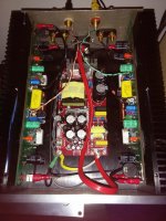
All in all, I'm pretty happy with it. Attached is the photo of how it's wired up at the moment. When I go to sort the power switch I'll tie everything down properly and trim off the excess on the speaker leads, and run the mains power lead under the smps. Current winning idea is a 'hidden' illuminated power switch on the bottom plate just near the front, so I can keep the clean front panel.
All in all; Good! what about yourself?
Edit - please note the crappy fuses, improvised back panel, and 'quality' parts used.
Hi Kris, yeah, all good so far.
I'm playing a bit of rock (Them Crooked Vultures) through a set of fullrangers (my favorite speakers - a set of Cain and Cain Abbey clones) at the moment, and I for one can't pick an absence of bass like some others commented with a SMPS. Criticalish listening to Jazz and old blues stuff has been great, and a set of more 'normal' speakers and playing rock has been enjoyable as well.
I've had it turned on for about the last week solid, so I reckon thats a tick for reliability as well. I haven't actually put a switch on it as yet either, so this hasn't been an act of deliberate stress testing as such
There is still a bit of a turn on pop, but it's not too bad with the speakers I'm using, and given they're quite sensitive that's pretty good. I used some actual K170's I had on hand that probably weren't fakes and were only a little higher in Idss that the ideal, so I didn't bother changing anything else on the front end of the amp, and that is probably the key part for sorting the turn on thump. I'm sure it could be improved, but for now I'm pretty happy. The heavy tracks on the board actually made it really hard for me to remove parts later on, so there was much swearing in making the alterations I did. I'm not overly keen to risk damaging the pcb to do anything further given it sounds pretty good now.
The heatsinking is more than sufficient so far, but I can't say I've really cranked up the amp to the limits as yet. I'm tempted to push for a bit more bias as per my original plan, but she's supposed to be my summer amp, so perhaps I won't bother there either! I probably need to sit down and do a pile of testing and see if anything comes up. I suppose stress testing on the bench for a while would be in order as well; just to make sure I don't BBQ a speaker at some point; I wasn't able to squeeze a protection circuit and relays in there, so it'd be wise to destruction test it!
All in all, I'm pretty happy with it. Attached is the photo of how it's wired up at the moment. When I go to sort the power switch I'll tie everything down properly and trim off the excess on the speaker leads, and run the mains power lead under the smps. Current winning idea is a 'hidden' illuminated power switch on the bottom plate just near the front, so I can keep the clean front panel.
All in all; Good!
what about yourself?Edit - please note the crappy fuses, improvised back panel, and 'quality' parts used.
Attachments
Last edited:
I think it's in one of my earlier posts - bear with me a moment. Note its a +/- 25 supply!
Edity goodness - http://www.ebay.com.au/itm/25V-200W...ctronics_Audio_Amplifiers&hash=item1c37f48629 or failing that search ebay for ' ±25V 200W, ±15V 5W digital amplifier switching Switch power supply board '
Edity goodness - http://www.ebay.com.au/itm/25V-200W...ctronics_Audio_Amplifiers&hash=item1c37f48629 or failing that search ebay for ' ±25V 200W, ±15V 5W digital amplifier switching Switch power supply board '
Last edited:
Happy to hear that!Hi Kris, yeah, all good so far.
All in all; Good!
Well, i have some 4700uF caps on order, and am going to implement a inrush current limiter between the SMPS and the amps, along with a DC protection and speaker relays(all solid state), but it's perfectly playable in its current condition, except the SMPS struggles a bit at turn-on.
I'll probably give it a whirl again soon in its finished enclosure, if nothing else to try to get some meaningful readings from the VU meters(read: dancing needles, absolutely no need for accuracy).
Hopefully when i'm back from holiday i'll knock out a fully working amp with all the bells and whistles!
I'm kind of reserving judgement till I go and measure the thing There's been enough said about the bass response with SMPS's in amps that there's bound to be a preconception in my mind biasing my feelings about the amp, however it sounds!
I just try to enjoy the pleasure of good music through something I made
There's been enough said about the bass response with SMPS's in amps that there's bound to be a preconception in my mind biasing my feelings about the amp, however it sounds!I just try to enjoy the pleasure of good music through something I made
I have carried out a little initial testing on two 95W smps.
Like left running overnight with a 50% of rated loading.
Like measuring the voltage change when connecting a load varying between 0% and 100% of rated power.
Like starting up with 10mF connected as the load (but with 2r0 as a current limiter, I have not tried lower than 2r0, I started with 20r).
So far no breakdowns.
The claimed power of 95W is not met.
15Vdc to 20Vdc <=4.5Adc
22Vdc or 24Vdc <=3.5Adc
The maximum output using those values is 90W @ 20Vdc, but substantially less at the other output voltages.
I have also looked at the output using a scope.
The spikes on the outputs are atrocious, both at low loading (0% & 5%) and at medium loading (~50%).
- Status
- This old topic is closed. If you want to reopen this topic, contact a moderator using the "Report Post" button.
- Home
- Group Buys
- FetZilla groupsbuy 5