Interesting plots. Can you explain the meaning of the reduced "field"? How do we interpret them?
Hi Dave,
For me, one of the revelations of working with FEMM was that often sims didn't look like I imagined they should! I guess the particulars of magnetism aren't easily grasped through common sense--at least by me. All the more reason for me to rely on simulations.
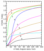
Regarding your question, I would say it's just Lenz' Law at work. As the moving flux field of the AC in the voice coil begins to penetrate the shorting rings, it is largely canceled by reciprocal flux of the currents it induces there. The squeezed, spatially reduced voice-coil field you see in the plot of the treated motors is the net product of those interactions.
They work especially well there partially because with the undercut pole (necessary to put the ring there) makes the inward stroke act more like the outward, since it eliminates the inductance effect of this pole section, just as the outward stroke approximates an aircore to some extent. Not that I'm telling you anything you woudn't know but useful for others perhaps. A T-shaped extended pole would probably improve the symmetry further in most cases.
A (DIY
") ) phase plug made of steel (at least the lower part of it ) can help a bit in the magnetic symmetry during outward cone movement, whether centre pole is T shaped or just cylindrical.
) phase plug made of steel (at least the lower part of it ) can help a bit in the magnetic symmetry during outward cone movement, whether centre pole is T shaped or just cylindrical.Regards
George
If a speaker is 1% efficient where does the other 99% go? Heat!
When I was developing the cooling plug for one of my basshorns, others pointed out that horns increase efficiency which, in turn, reduces heat. This is true, of course. But in even the best horns, there is still 50% to 75% of the input energy that ultimately becomes heat. And a basshorn reduces excursion, so the cooling vents don't work as well. The cooling plug approach is very effective in this situation, providing some additional heat transfer where the vents can't.
Regarding your question, I would say it's just Lenz' Law at work. As the moving flux field of the AC in the voice coil begins to penetrate the shorting rings, it is largely canceled by reciprocal flux of the currents it induces there. The squeezed, spatially reduced voice-coil field you see in the plot of the treated motors is the net product of those interactions.
So, clearly, the penetration of the field into the top plate and core pole is reduced, but isn't the distortion a byproduct of non-linearity of the magnetic material (hence ferrite having a problem that Alnico doesn't)?
This gets into areas where my knowledge is a little shaky.
David S.
When I was developing the cooling plug for one of my basshorns, others pointed out that horns increase efficiency which, in turn, reduces heat. This is true, of course. But in even the best horns, there is still 50% to 75% of the input energy that ultimately becomes heat. And a basshorn reduces excursion, so the cooling vents don't work as well. The cooling plug approach is very effective in this situation, providing some additional heat transfer where the vents can't.
Yes but if you go from 99% wasted as heat to 95% wasted as heat, that is still 5 times as efficient and 1/5 the input for a desired output. Big change.
David S.
isn't the distortion a byproduct of non-linearity of the magnetic material (hence ferrite having a problem that Alnico doesn't)?
The typical steel alloys that guide the flux in most loudspeaker motors also have quite nonlinear BH curves, and this interacts in series with the BH curve of the magnet itself, especially at low frequencies. At higher frequencies where eddy currents in the return circuit close to the voice coil come into play, I would suppose the BH curve of the magnet contributes less distortion.
Magnetized NdFeB has quite a linear BH curve. I don't recall seeing the BH curve of AlNiCo, but I have heard it is more linear than that of magnetized Ferrite. In the olden days, a happy coincidence of using AlNiCo magnets was that the relatively high electrical conductivity of the material made the magnet itself function somewhat like a giant shorting ring.
Yes but if you go from 99% wasted as heat to 95% wasted as heat, that is still 5 times as efficient and 1/5 the input for a desired output. Big change.
Oh, absolutely. I'm definitely a proponent of horns. They offer so many benefits, with very little, if any, downside.
But my point is there is still a lot of heat inside the motor core of a prosound woofer, and when it's in a basshorn, excursion is reduced so the cooling vents lose their effectiveness.
The typical steel alloys that guide the flux in most loudspeaker motors also have quite nonlinear BH curves, and this interacts in series with the BH curve of the magnet itself, especially at low frequencies.
12L14 leaded steel is a particularly good solution here. It is it's own shorting ring and when used with Alnico makes for a very linear motor. Nestorovic Labs made use of this combo in their Model 16 woofer systems. The drivers were built from machined motor components and about 5 pounds of Alnico. Later the magnet was changed to Ferrite and was even bigger.
Bud
For midrange and up, it makes all kinds of sense to encourage eddy currents in shorting rings, steel motor parts and even the magnets (AlNiCo) to stabilize the operating points of the motor parts and magnet. The only catch is that eddy currents are going to be largely MIA at low frequencies, no matter how much you encourage them. So, when bass notes come, the operating points of your motor parts and magnet are still getting knocked around by the VC field, and their BH curves are imposing their transfer functions on the harmonic distortion spectrum.
At bass freqs., compensation coils--stationary counter-windings on the pole in parallel with the VC (ala 18Sound)--are effective, as is JBL's Differential Drive architecture, where two counterwound voice coils balance each other's induction.
At bass freqs., compensation coils--stationary counter-windings on the pole in parallel with the VC (ala 18Sound)--are effective, as is JBL's Differential Drive architecture, where two counterwound voice coils balance each other's induction.
Last edited:
there is still a lot of heat inside the motor core of a prosound woofer, and when it's in a basshorn, excursion is reduced so the cooling vents lose their effectiveness.
An OT digression, but I wonder if anyone's ever tried using heat pipes? They can be made quite simply with copper tubing, acetone and some basic soldering. Seems to me you could friction-fit the evap. end into a pole vent and mate the condensing end to a heatsink outside the enclosure.
Here's a how-to link.
Last edited:
An OT digression, but I wonder if anyone's ever tried using heat pipes? They can be made quite simply with copper tubing, acetone and some basic soldering. Seems to me you could friction-fit the evap. end into a pole vent and mate the condensing end to a heatsink outside the enclosure.
The Japanese have done it. We looked into it for the KEF KM1 midranges and found it was cheaper to use a large solid aluminum cylinder to a heatsink on the back of the cabinet.
I think someone also did a heat pipe to heatsinks in the port tube: forced air flow.
David S.
For midrange and up, it makes all kinds of sense to encourage eddy currents in shorting rings, steel motor parts and even the magnets (AlNiCo) to stabilize the operating points of the motor parts and magnet. The only catch is that eddy currents are going to be largely MIA at low frequencies, no matter how much you encourage them. So, when bass notes come, the operating points of your motor parts and magnet are still getting knocked around by the VC field, and their BH curves are imposing their transfer functions on the harmonic distortion spectrum.
At bass freqs., compensation coils--stationary counter-windings on the pole in parallel with the VC (ala 18Sound)--are effective, as is JBL's Differential Drive architecture, where two counterwound voice coils balance each other's induction.
In my experience the midrange magnet hysteresis distortion is the one to tackle. At low frequencies distortion is dominated by standard motor non-linearity. The JBL curves above back that up.
By the way, constant current drive lowers the magnet hysteresis distortion. I did tests with a high output impedance amp and midrange distortion dropped. LF distortion did not.
David S.
Wow, Dave, you were part of the KM1 design team? That must have been so much fun! I'm a sucker for gonzo, no-compromise engineering exercises like that. I consider that type of thing an ultimate form of human artistic expression. Luv it!
Re: heat pipes--I like the idea of putting the condensing end of a heat pipe into a port--put that moving air to work! Only downside might be subtle shifts in tuning as port air density changes with temperature...
Bill
Re: heat pipes--I like the idea of putting the condensing end of a heat pipe into a port--put that moving air to work! Only downside might be subtle shifts in tuning as port air density changes with temperature...
Bill
In my experience the midrange magnet hysteresis distortion is the one to tackle.
I'm very curious--how did you isolate the variable of magnet hysteresis from the variable of hysteresis in the steel return circuit? In most motor architectures, there's quite a bit of steel between the voice coil and the magnet, and it's exposed to stronger VC fields where its significant remanence means hello there, hysteresis! So I'm surprised and intrigued that the magnet's hysteresis effects overwhelm those of the steel. Especially in the midrange where eddy currents in the steel are reducing the effective "reach" of the VC field into the motor parts.
P.S. After about a decade of posting here, I still don't know how to make quote boxes with the cool "originally posted by... + link." I feel like an idiot. Can someone please let me in on the secret?
Last edited:
At low frequencies distortion is dominated by standard motor non-linearity.
This is true. Even if you had an impossibly perfect magnetic circuit, there's still the challenge of how well the soft parts handle excursion. Can't forget the forest for the trees.
(Hey, I just crossed 1k posts!)
Last edited:
I'm very curious--how did you isolate the variable of magnet hysteresis from the variable of hysteresis in the steel return circuit? In most motor architectures, there's quite a bit of steel between the voice coil and the magnet, and it's exposed to stronger VC fields where its significant remanence means hello there, hysteresis! So I'm surprised and intrigued that the magnet's hysteresis effects overwhelm those of the steel. Especially in the midrange where eddy currents in the steel are reducing the effective "reach" of the VC field into the motor parts.
Actually an assumption on my part since it is clear that ferrite structures have a problem and alnico structures don't.
I thought steel was linear if you are well under saturation? Typically we design to stay below saturation so as not to waste magnet energy.
I am not an expert on this subject!
David S.
I'm no expert either, but my understanding is that B-H linearity in steel loudspeaker motor parts is a relative thing, and it depends on a lot of variables--such as the alloy in question, the flux density it's carrying from the magnet, etc. There can be two ranges of relative linearity in the B-H curve--below saturation under the "knee," and into saturation above the "knee." Under the dynamic conditions of loudspeaker operation, either of these linear ranges are easily violated as VC current alternately adds to the magnet's flux (drives the steel's operating point deeper into saturation) and then pushes against the the magnet's flux, sometimes going as far as to momentarily reverse the flux flow through parts of the steel return circuit.
Steel seems at best a necessary evil in loudspeaker motors.
I don't doubt that AlNiCo has some inherent advantages over ferrite, at least in its higher conductivity (functioning as a shorting ring) and possibly in its operating-point behavior under dynamic conditions--I don't know for sure.
Steel seems at best a necessary evil in loudspeaker motors.
I don't doubt that AlNiCo has some inherent advantages over ferrite, at least in its higher conductivity (functioning as a shorting ring) and possibly in its operating-point behavior under dynamic conditions--I don't know for sure.
And now for something completely different!
Instead of using shorting rings to encourage eddy currents and reduce Le, ATC goes the opposite direction--minimizing eddy currents and deliberately increasing Le by lining the magnetic gap with a magnetic material that features high resistivity (they call it SLMM).
Here's an excerpt from ATC's company profile and technical philosophy paper:
There aren't very many specifics here... So whaddaya think? Truth or audiophile pseudo-science mumbo-jumbo?
It's an interesting thought that the same summit--reduced motor distortion--might be approachable from two opposite sides of the mountain...
Instead of using shorting rings to encourage eddy currents and reduce Le, ATC goes the opposite direction--minimizing eddy currents and deliberately increasing Le by lining the magnetic gap with a magnetic material that features high resistivity (they call it SLMM).
Here's an excerpt from ATC's company profile and technical philosophy paper:
The third source of distortion is due principally to the inherently non-linear magnetic performance of steel. The alternating magnetic field created by the voice coil induces eddy currents into both the pole and front plate, adjacent to the coil, of the permanent magnet assembly. These eddy currents flow in such a way as to oppose the magnetic field producing them, (i.e. from the voice coil), and cancel out much of the self inductance. This mechanism is minimized in ATC bass and bass/mid drive units by the use of a new material, which has the unique properties of high magnetic permeability and saturation as well as low electrical conductivity.We call it a super linear magnet material (SLMM). With this material fitted to the pole and front plate adjacent to the voice coil the eddy currents are suppressed and the impedance (self inductance) increases. The result is that third harmonic distortion is reduced by between 12–15dB.
There aren't very many specifics here... So whaddaya think? Truth or audiophile pseudo-science mumbo-jumbo?
It's an interesting thought that the same summit--reduced motor distortion--might be approachable from two opposite sides of the mountain...
More specifics from and earlier ATC paper:
I wonder why they left the magnet un-energized? Energizing the mag moves the hysteresis set point by magnetic "biasing." Seems closer to the real world...
Experiments were performed on a blocked voice coil with the magnet left un-energised. It could be thought of as a cored inductor. A current was passed through the coil and second and third harmonic distortion components were measured. Mathematical analysis, in conjunction with the experiments, has revealed some surprising answers to the question of why replacing the steel regions with S.L.M.M. has such a dramatic effect on the distortion.
(Snip)
...the presence of the S.L.M.M. increases the self-inductance of the voice coil. When eddy currents are allowed to circulate in the system, they oppose the magnetic field producing them (i.e. that from the coil) and ‘cancel out’ much of the self-inductance. With the S.L.M.M. in place, eddy currents are suppressed and the self-inductance (i.e. the impedance) goes up. thirdly, whilst the impedance, and therefore the fundamental voltage across a blocked coil goes up when the rings are fitted, the harmonic components, that are induced back into the voice coil, stay the same. This is because they are dependent only on magnetic field, which as we have seen, doesn’t change very much. The net effect is a rise in the signal/distortion ratio.
I wonder why they left the magnet un-energized? Energizing the mag moves the hysteresis set point by magnetic "biasing." Seems closer to the real world...
Last edited:
- Status
- This old topic is closed. If you want to reopen this topic, contact a moderator using the "Report Post" button.
- Home
- Loudspeakers
- Multi-Way
- Faraday ring in louspeaker driver, what is it?