You could put quite a few of those transformers in one of the small International priority mail boxes. They weigh 3.5oz each box (max 4 lbs a box at 16oz per pound). Could still add some bubble wrap padding on them.
I added the R100A and transformer size for perspective, with a little help from my therapist, Dr. Freud. So four of them don't need two of the boxes Generg if that's what they said.
Oh tea-bag,
Now I understand why you are such a wise man.....

Still have oscillation
Forget the 2-pole filter, it also will oscillate. With zero input the output offset will slowly wonder up and down about 10mV at a rate of about .5Hz.
With the original 1-pole filter built with 22uF and 20K ohms, when I input a 1Hz signal at .5V the amplifier with oscillate to the rails even after the signal is removed.
Nelson: Does your build of the "official" F6 exhibit this problem?
.....
Zen Mod: Is the mission to unravel Conceptual F6 accomplished? Where to next? What are the upcoming hurdles? Your thoughts.
Pa gave enough of Real McCay , so I think it can be made now no shy to original one
I can help you with the answer I got on my request some time ago
Thx for the info.
G.- did you received repeaters?
Not yet, but I think they will come these days....
Pa gave enough of Real McCay , so I think it can be made now no shy to original one
Which DIYer has the closest copy of Mr. Pass's F6? There are tens of thousands of DIYers out there; but there can only be a few suitable solutions to F6. At best; no more than 5-10.
- lhquam
- kasey197
- triode_al
- bobodioulasso
- loudthud,flg, Rush and buzzforb ; are you in the running too?
Last edited:
lhquam: Does it also oscillate with the 2-pole filter; but without loop feedback?Forget the 2-pole filter, it also will oscillate. With zero input the output offset will slowly wonder up and down about 10mV at a rate of about .5Hz.
With the original 1-pole filter built with 22uF and 20K ohms, when I input a 1Hz signal at .5V the amplifier with oscillate to the rails even after the signal is removed.
Nelson: Does your build of the "official" F6 exhibit this problem?
Which DIYer has the closest copy of Mr. Pass's F6? There are tens of thousands of DIYers out there; but there can only be a few suitable solutions to F6. At best; no more than 5-10.
- lhquam
- kasey197
- triode_al
- bobodioulasso
- loudthud,flg, Rush and buzzforb ; are you in the running too?
Probaby "the one and only".
By "without loop feedback" do you mean full open-loop gain, no feedback network? I haven't tested that situation, but Spice suggests no oscillation with 1-pole, possibility with 2-pole.lhquam: Does it also oscillate with the 2-pole filter; but without loop feedback?
Please break the feedback connection [all of the underlined] to the bottom lead of the primary. Suppose it does not oscillate. Will it be resolved by decreasing the amount of feedback to the front end, and/or increasing degeneration in the output devices? You have a good theoretical grip on these matters of feedback per an earlier post to kasey197.By "without loop feedback" do you mean full open-loop gain, no feedback network? I haven't tested that situation, but Spice suggests no oscillation with 1-pole, possibility with 2-pole.
Nelson: Does your build of the "official" F6 exhibit this problem?
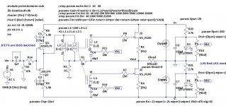
No. Assuming that this is real and not a sim, what is the exact schematic
you used?
I just re-verified that the circuit built to this schematic will oscillate about about .5Hz when stimulated by about .5V at .5Hz.No. Assuming that this is real and not a sim, what is the exact schematic
you used?
Correction: The input cap is not shorted in the circuit tested.
Attachments
Last edited:
I just re-verified that the circuit built to this schematic will oscillate about about .5Hz when stimulated by about .5V at .5Hz.
Correction: The input cap is not shorted in the circuit tested.
Wow:
I just re-ran the Spice simulation with the input cap not shorted, and the phase margin goes from 74 degrees (good) to 28 degrees (very bad).
I will retest the build with the cap shorted.
The problem has been the input cap all of this time. I had it in the circuit to avoid DC through the transformer (The input JFETs were IDDS matched).
I expect a field day [more like a week to a month] of analyzing the one and only F6 schematic of Mr. Pass.Probaby "the one and only".
lhquam: you wrote above:
"The problem has been the input cap all of this time. I had it in the circuit to avoid DC through the transformer (The input JFETs were IDDS matched). "
The value of the input capacitor in your schematic is 1uF. Will it still be a problem if it were 10 to 100 uf instead? Can one use input caps in your schematic, and ones of values greater than 1uF?
Will the oscillation problem worsen with an input cap of value equal to 0.1uF?
Last edited:
Another difference between the circuit that oscillated and the schematic: The oscillating circuit had 1uf input cap with 100k resistor to ground, not 47k as shown. Here are LTSpice computed values for the phase margin.lhquam: you wrote above:
"The problem has been the input cap all of this time. I had it in the circuit to avoid DC through the transformer (The input JFETs were IDDS matched). "
The value of the input capacitor in your schematic is 1uF. Will it still be a problem if it were 10 to 100 uf instead? Can one use input caps in your schematic, and ones of values greater than 1uF?
Will the oscillation problem worsen with an input cap of value equal to 0.1uF?
Input Cap Res to Gnd Phase Margin
1uf 100k 28 deg
1uf 47k 50 deg
.5uf 47k 74 deg
I would say: go with .5uf and 47k.
On the other hand, the AC analysis that gives phase margin is from input to output. The actual feedback loop is not affected by the choice of the input capacitor and still has the underlying low frequency instability.
I will redo the tests for the actual build.
Last edited:
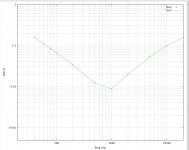
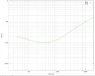
I just re-tested the circuit shown #1173 with the input cap shorted. No oscillation. I also ran tests on the 2-pole filter version shown here which did not oscillate with the input cap shorted.
Here are THD vs. frequency sweeps. As you can see, the 2-pole filter helps a lot at low frequencies.
How about putting a potentiometer in place of the resistor R12 between the 2 filter caps? That way you can pick the level of low frequency distortion you like.
Here are THD vs. frequency sweeps. As you can see, the 2-pole filter helps a lot at low frequencies.
How about putting a potentiometer in place of the resistor R12 between the 2 filter caps? That way you can pick the level of low frequency distortion you like.
Attachments
Last edited:
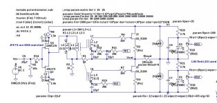
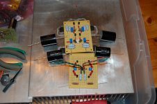
I got mine 90% done. Started out wrong and did input stage like F5, but with signal coming out after 10ohm Rs of Jfets. Got the pot for offset trim. I used BA-1 style bias circuit, dropping teh resistor for Jfet ccs feeding 3 led string. This has parallel 10uF cap and feeds a 5K pot for gate bias. basically looks like Bodu's circuit. I am using laterals instead of SS. Have to reduce feedback resistor since i dont think Laterals will give em much gain to work with. Thinking about overall gain of about 10.
Attachments
Wow:
I just re-ran the Spice simulation with the input cap not shorted, and the phase margin goes from 74 degrees (good) to 28 degrees (very bad).
I will retest the build with the cap shorted.
The problem has been the input cap all of this time. I had it in the circuit to avoid DC through the transformer (The input JFETs were IDDS matched).
I have a difficult time believing that the input cap is the culprit. The input impedance of those Jfets ought to be
way high compared to the input network.
- Home
- Amplifiers
- Pass Labs
- F6 Amplifier