These are fine transformers, but a bit pricey.
I would personally consider the line input LL1540 which is cheaper. Difference is the DC resistance is in the 600-800 ohm range per winding, which I don't believe is a problem which also means you could omit the gate stoppers.
You might get a slight LF roll-off, maybe you can simulate to check it's not too much.
I've not checked if the pinouts are the same.

One might want to look for as low winding resistance as possible.
HF-response will suffer if high winding resistance at the transformer.
Line input transformers are probably not the best choice.
I have LL1517 on my table, just waiting for a new PCB.
Will put a diamond to drive them, just to have sufficient gate drive muscle for the fets.
I have simulated with a transformer of 1H and 600Ω per winding and there's very little LF and HF roll-off. The F6 does have a jfet buffer in front of the transformer..
Attachments
Last edited:
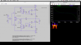
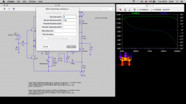
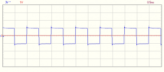
F6 with Lundahl 1527 and Cree C2M0280120D. 26.5V rails, LCLC supply, 1.2A bias. 8 Ohm load resistor:
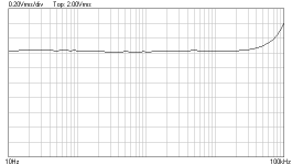
Frequency sweep 10Hz to 100kHz sine wave 0.5Vrms
Frequency sweep 10Hz to 100kHz sine wave 2.0Vrms
Square wave 1kHz 0.5Vrms
Square wave 1kHz 2.0Vrms
Frequency sweep 10Hz to 100kHz sine wave 0.5Vrms
Frequency sweep 10Hz to 100kHz sine wave 2.0Vrms
Square wave 1kHz 0.5Vrms
Square wave 1kHz 2.0Vrms
Attachments
Wonderful Kaputt this is exactly what I wanted to see!
I too am using the Cree's with similar supply but with the Jensen transformer and my response curve is identical to Nelsons, starts to dip after 20KHz
Can you do me a favour and run the square wave test at say 10KHz and 60KHz if the waveforms show significant improvement than Jensens then I will get some Lundahls.
Again thanks for taking the time and posting.
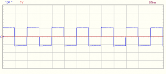
F6 with Lundahl 1527 and Cree C2M0280120D. 26.5V rails, LCLC supply, 1.2A bias. 8 Ohm load resistor:
Frequency sweep 10Hz to 100kHz sine wave 0.5Vrms
Frequency sweep 10Hz to 100kHz sine wave 2.0Vrms
Square wave 1kHz 0.5Vrms
Square wave 1kHz 2.0Vrms
I think you have taken only a 1 probe measurement without taking into account the signal generator error at its output.
You need to use 2 probes. 1 at signal generator output and 1 at amplifier output.
Also suggesting measures at 4Vpp output to make it comparable with others (1W/8ohm)...
But, maybe I am wrong.
One might want to look for as low winding resistance as possible.
HF-response will suffer if high winding resistance at the transformer.
Are you talking about resistive influence on the circuit around the transformer or about HF response of the transformer itself? The limiting factor in the the transformer itself is the interwinding capacitance. This of course gets lower with less windings which also cuts down on resistance.
Hi Chatziva the Cree C2M0160120D is exactly what I have in my F6 running at 1.4 Amps bias.
I had put my signal generator on the F6 and it produced exactly the same frequency response curve as Nelson had shown in his article. He mentioned the frequency response was indeed governed by the transformer so my interest is seeing what other people are going to use and the outcome. I used the C2M0160120D due to it's lower input capacitance in the hope the frequency response would be extended slightly but it has been found not to be the case.
If I look at the spec sheets for the transformers the Jensens appear better on paper but what I'm seeing so far from Kaputt would indicate differently.
Gotta love this hobby")
I had put my signal generator on the F6 and it produced exactly the same frequency response curve as Nelson had shown in his article. He mentioned the frequency response was indeed governed by the transformer so my interest is seeing what other people are going to use and the outcome. I used the C2M0160120D due to it's lower input capacitance in the hope the frequency response would be extended slightly but it has been found not to be the case.
If I look at the spec sheets for the transformers the Jensens appear better on paper but what I'm seeing so far from Kaputt would indicate differently.
Gotta love this hobby
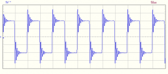
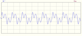
Thanks Kaputt I'm sure there will be other people jumping in here and commenting on the waveforms especially the 60KHz one. If you have not changed the scales of your scope on the 60KHz one then we can clearly see the frequency is definitely having an effect on the output and it does not correlate with the flat frequency response you have shown in the first diagram.
I changed the scales as I went for best visibility of the distortion at 60kHz. Level correlates to the frequency response plot.
As to the "sound" question asked earlier: so far I only had a chance to listen to the amp through horrible Scan Speak Illuminators but even with these it had some kind of "swing" but I wasn't instantly taken away. I'll get back to that after listening with different speakers.
As to the "sound" question asked earlier: so far I only had a chance to listen to the amp through horrible Scan Speak Illuminators but even with these it had some kind of "swing" but I wasn't instantly taken away. I'll get back to that after listening with different speakers.
Last edited:
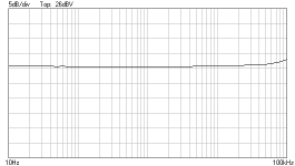
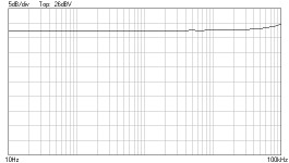
Frequency response at 4Vpp output into 8 Ohm resistor.
Square wave response 10kHz and 60kHz.
The rising response at 100k is a little worrying.
Increase sweep to 1 MHz to see the full picture.
Thanks for jumping in Nelson, looking as the Lundahl Data sheet for high frequency performance one does indeed need resistance
"Static resistance of each primary: 43Ω 54Ω
Static resistance of each secondary: 56Ω 67Ω
Distortion (primaries connected in series, source
impedance 800Ω ):
+ 6 dBU 0.1% @ 50 Hz + 9 dBU 0.1% @ 50 Hz
+16 dBU < 1 % @ 50 Hz +19 dBU < 1 % @ 50 Hz
Self resonance point : > 200 kHz > 200 kHz
Optimum load for best square-wave response
(sec. in series):
3 - 4 kΩ 3 - 4 kΩ
Frequency response (source 800Ω , load 4 kΩ
serial connection):
10 Hz -- 150 kHz +/- 0.2 dB 10 Hz -- 150 kHz +/- 0.2 dB"
Does this mean placing resistors across the secondaries of the transformers as well as lowering the gate stopper resistors?
- Home
- Amplifiers
- Pass Labs
- F6 Amplifier