the Cree C2M0160120D is exactly what I have in my F6
They look great on paper. Also I am thinking they would be ideal for biasing with a single LED!
Thanks for jumping in Nelson, looking as the Lundahl Data sheet for high frequency performance one does indeed need resistance
"Static resistance of each primary: 43Ω 54Ω
Static resistance of each secondary: 56Ω 67Ω
Distortion (primaries connected in series, source
impedance 800Ω ):
+ 6 dBU 0.1% @ 50 Hz + 9 dBU 0.1% @ 50 Hz
+16 dBU < 1 % @ 50 Hz +19 dBU < 1 % @ 50 Hz
Self resonance point : > 200 kHz > 200 kHz
Optimum load for best square-wave response
(sec. in series):
3 - 4 kΩ 3 - 4 kΩ
Frequency response (source 800Ω , load 4 kΩ
serial connection):
10 Hz -- 150 kHz +/- 0.2 dB 10 Hz -- 150 kHz +/- 0.2 dB"
Does this mean placing resistors across the secondaries of the transformers as well as lowering the gate stopper resistors?
I dont think one must put 4kohm load on them but some sort of rc-load is good I think.
F6 build,
let cook for 4 hours biased the amps at 0.610v with offset of 2 to 3 mv FETS got up to 50 c.
Testing at 1 khz with meters, signal generator, and Scope.
Power supplies at full bias +- 22.2v
No load clipping 41.2 v peak to peak
Measurements with 4 ohm load, voltages are peak to peak from scope at 1KHz.
Left channel
Input Output Bias
0.29v 1.37v 0.606
2.84v 13.45v 0.618
5.66v 26.15v 0.67
Right channel
Input Output bias
0.286v 1.43v 0.605
2.84v 13.7v 0.615
5.65v 27.15v 0.67
At soft clipping top of sine wave just starting to change shape.
6.5-7.6v 34-36v 0.8+ Left
6.5-7.6v 34-36v 0.8+ Right
Let smoke out of right channel 0.47 ohm resistor. All measurement with one channel driven.
Measured current on one channel with meter 10 to 12 amps at soft clipping.
The preamp will need to output around 4 to 5 volt RMS to achieve full output from the amp at current gain setting, which may be a problem for some pre’s. Also if you are going to drive 4 ohm or lower loads at close to full output then need to parallel the bias resistors to get 6 watt or higher wattage. May be a good fit for Caddock resistors (May try to order some to try out).
My measured gain left was 4.73 or 13.49db and right was 4.82 or 13.66db according to F6 article gain was set to 5 with a 50kz bandwidth, my question is does anyone know what the bandwidth would be with a gain of around 7 or 16-17 db.
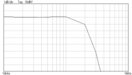
Frequency response at 4Vpp output into 8 Ohm resistor.
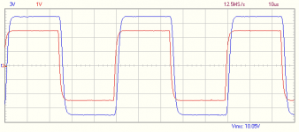
Square wave response 10kHz and 60kHz.
I "quickly" threw together a Lundahl F6 from what I had on hand.
Transformer: LL1517
Buffer: Diamond BD139/140
Output: IRFP140
Gain: 20x (100R/4.7R)
Bias: 660mA
Frequency response is similar to Kaputts findings.
It also has a similar transformer ringing in it.
1kHz/8R/1W THD is 0.07%, which is not too bad, I think. Taking into account the gain, the bias and that the Diamond still needs some fine tuning; I believe I can get it below 0.05% quite easily.
All in all, very perfectible concept...
...more to come...
Attachments
Probably a little less ringing with this setup.
60kHz SQR, red in, blue out.
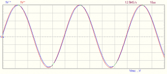
The 20kHz sine is quite beautiful though...
Im not too sure if I need to be too worried about the ringing, but lets see if there is something that can be done about it...
60kHz SQR, red in, blue out.
The 20kHz sine is quite beautiful though...
Im not too sure if I need to be too worried about the ringing, but lets see if there is something that can be done about it...
Attachments
I "quickly" threw together a Lundahl F6 from what I had on hand.
Transformer: LL1517
Buffer: Diamond BD139/140
Output: IRFP140
Gain: 20x (100R/4.7R)
Bias: 660mA
Frequency response is similar to Kaputts findings.
It also has a similar transformer ringing in it.
1kHz/8R/1W THD is 0.07%, which is not too bad, I think. Taking into account the gain, the bias and that the Diamond still needs some fine tuning; I believe I can get it below 0.05% quite easily.
All in all, very perfectible concept...
...more to come...
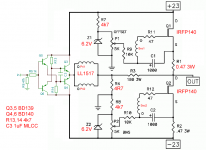
Interesting ! Do you have a schematic for this ?
Do you have a schematic for this ?
Well...
I have now! ;-)
Its a keeper if I can get the THD around 0.02% with minimal ringing at the same time. Looks like 200kHz... Shouldnt be a problem. I will probably snubberize it at the trafo secondaries.
Or, cut the HF from feedback. Or both.
Lets see...
Attachments
Very nice mod there, well done!
With respect to transformer ringing, some Lundahl transformers give various schemes in order to filter it.
E.g. for the LL1540 a 22kΩ + 1nF network or 17.5kΩ resistors across the secondaries are recommended.
http://www.lundahl.se/wp-content/uploads/datasheets/1540.pdf
Papa uses a 10kΩ + 680pF network on the M2, which uses an Edcor 600/15K PCB transformer.
I believe the formula for calculating the cutoff freq. is f=1/(2*pi*R*C)
Last edited:
Its a keeper if I can get the THD around 0.02%...
Well...
That was easy.
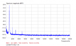
The best I was able to squeeze from the Jensens was 0.009% at 2A bias or something.
This goes easily to 0.005% already at 1.3A (1kHz/1W/8R)!
Note: Gain 20x !!!
Definitely a keeper.
Attachments
Nice !
So if I'm get it right your Q3,4,5,6 is BD139/140 as input/ buffer stage ?
Yes
Well...
That was easy.
The best I was able to squeeze from the Jensens was 0.009% at 2A bias or something.
This goes easily to 0.005% already at 1.3A (1kHz/1W/8R)!
Note: Gain 20x !!!
Definitely a keeper.
You've been busy...! Congratulations!
...with minimal ringing at the same time. Looks like 200kHz... Shouldnt be a problem...
Oh!
Gate resistors 390R.
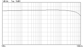
Took care of the ringing. Made the freqres nice and flat.
Will check tomorrow, if that also killed the 5th harmonic.
But now its beer time!
")
Attachments
If it is not too much headache what is open loop bandwidth?
You mean open loop gain?
Not measured it yet, could measure that when I start with the 2nd channel...
Have not tested the full power bandwidth either...
Anyways,
I have results for the new gate stoppers.
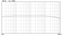
Not too happy... I already fell in love with the 0.005% and because of the resistor change it is now 0.011% (still not bad, but...), and that mainly because of the increased 3rd harmonic only!
What is interesting is that the 5th did not change at all! It stays rock solid on -100dB???
This goes over my brain capacity.
So, any bright ideas anyone?
Or,
5th harmonic at -100dB? Who cares?
I will put 220R gate stoppers there next, and if no ringing, will stick with those.
Should at least lower the 3rd harmonic back to an "acceptable" level..
This is fantastic news palstanturhin thank you for taking the time and effort to research this.
So just so I understand this correctly in the original F6 article Nelson had showed that by increasing the overall gain the frequency response did increase but was not flat as you have shown.
Using your excellent Diamond buffer which obviously has lower output impedance you were able to drive the Lundahl better even though on paper the Jensens have a better specification.
I use a high speed buffer chip HA5002 which has a very low output impedance and was hoping to get and increased frequency response by it's use together with the Jensen but as you have clearly shown the Lundahls are indeed better. You do not show on your schematic the RC network supposedly needed for frequency compensation as per Lundahl recommendations have you indeed done this?
Moving on to the the gate stoppers I'm not sure I fully understand their purpose but you have shown that by increasing the resistance from 47ohm as in the original to now 220 ohms you can tame the ringing of the square wave.
This is all fascinating stuff and what diy is all about and I learn so much from this forum keep going guys!
Ah... I c.I mean open loop frequency response?
Does it exceed 20kHz without feedback?
No, I have not measured that, but yes, it does exceed 20kHz...
Will check that later, though.
This is fantastic news palstanturhin thank you for taking the time and effort to research this.
So just so I understand this correctly in the original F6 article Nelson had showed that by increasing the overall gain the frequency response did increase but was not flat as you have shown.
Using your excellent Diamond buffer which obviously has lower output impedance you were able to drive the Lundahl better even though on paper the Jensens have a better specification.
Yes.
Compared to the JFET buffer, You most likely will get a itsy bitsy better frequency responce with the HA5002. I myself was considering LME49610 at one point, but TI decided differently.I use a high speed buffer chip HA5002 which has a very low output impedance and was hoping to get and increased frequency response by it's use together with the Jensen but as you have clearly shown the Lundahls are indeed better.
No. No snubber at the secondaries.You do not show on your schematic the RC network supposedly needed for frequency compensation as per Lundahl recommendations have you indeed done this?
Moving on to the the gate stoppers I'm not sure I fully understand their purpose but you have shown that by increasing the resistance from 47ohm as in the original to now 220 ohms you can tame the ringing of the square wave.
Yes.
The gate stoppers form the needed RC network together with the MOSFETs internal gate capacitance.
We can use that to our advantage.
An external snubber network would put additional stress to the input buffer. That of course would also not be a problem.
The ideal gate stoppers for IRFP140 output stage in this circuit seems to be 240 or 250R.
I dont have those, so I keep the 220R.
If different output stage MOSFETs, one needs something else here, as we all know...
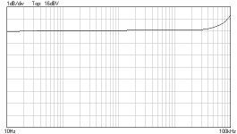
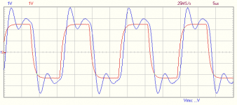
Some graphs with the new 220R gate stoppers,
20kHz square wave,
and full power frequency response.
"Full Power" means 17W. My PSU is only +/-20V.
Attachments
- Home
- Amplifiers
- Pass Labs
- F6 Amplifier