You say the F6 commercial version is different from the one given to diyer's. I did not know you had privileged information none of us have.
Decoupling caps just to name 1 difference
I did not think Nelson would think it necessary to comment on your telling the forum you think he just made a mistake or forgotten to make changes and that you are correct. It would be a waste of his valuable time. I am sure you will provide more rhetoric and confuse more beginning builders and the more knowledgeable builders will just ignore you as I probably should.
Here is Nelson's response to my queries/observations.
He made the cap location modification to an existing circuit which already had the values of 0.56 and 0.47 Ohms in it.
No, I simply made the cap location modification to an existing circuit whose
Source resistors reflected the desire for some 2nd harmonic by different
degeneration top vs bottom.

He never disagreed with my observations: Which is, to get the full degenerating effect for 2nd harmonic adjustment, you need to move the cap lead to the other side of the source resistor as it is published in the original F6 article.
I don't see a reason to appologise. Nelson didn't have an issue with anything I have stated when he responded
Last edited:
I am sure your equipment in your lab is far superior to what Nelson uses at Firstwatt and of course there is nothing in your observations in simulation and with your superior equipment and testing that you have not thought of or not made a mistake in with your superior electronic background. Only someone with your equipment and knowledge would even think of telling the forum Nelson made a mistake.
You are one very special individual. I enjoyed that personal attack, I think it could have been done a little better though.
I'll add you to my ignore list, right now.
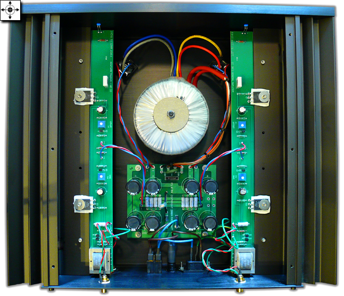
Pic above is of Semisouth version. My personal favorite used these fets with no degeneration on top and only a little(around .05-.1R) on the bottom. When I say degeneration, I am meaning the AC type(cap below resistor, including its effects). Lovely amp. Even went so far as to do a bridged/balanced version that was even more enjoyable. Now considering the bridged version with multiple outputs and Jfet drivers after the transformer(will allow dropping of caps).
I am curious as to what the second cap (one of two close together) does (where in the cct. it would be).I wonder if this was one of Nelson's early versions . There also seems to be a third cap at the center of the board.
The cap in the centre appears to be placed across the powersupply input.
The two caps together could be a parallel combo, but in my opinion one of them is most likely used across the zener/trimpot to get an absolutely noise free voltage source for Vgs adjustment.
Last edited:
Experimentation is good and trying different ways sometimes leads to changes that others find better sounding but it would be a far stretch to accuse a Master designer considered the best in his field as making a mistake. As I have stated an apology would be the gentlemanly thing to do and a statement like "to me the circuit changes I suggest has more of an effect with the 2nd harmonic" if that is what you truly believe instead of boldly stating that in your opinion Nelson just forgot something.
---------------------------------------------------------------------------------------
Have a good day sir.
You are one very special individual. I enjoyed that personal attack, I think it could have been done a little better though.
I'll add you to my ignore list, right now.
No personal attack, just stating the obvious. I did not think you would be smart enough to keep your mouth shut. No you just keep trying to prove you are right.
Nelson didn't forgot anything
any possible iteration is covered in initial article , published on 6moon
there is no dedicated article about later mosfet iteration , so crumbs and milestones everywhere
and ...... he's certainly not responsible for official DiyA F6 pcb , in any way or meaning
- crummy version of 6moon article attached , version with proper text layout is too big
Attachments
2 picoDumbs
I have nothing personally against you in fact I admire your electronic circuitry skills and your willingness to try something different. You are an asset to the forum and I have read everything you have wrote. I just take offence in you suggesting Nelson made a mistake and has forgotten something and changes in the circuit need to be made. The circuit and the sound is exactly as Nelson wanted it to be. No one has came out and said so but to my understanding the store boards are made as the last schematic of the F6 with the mosfet transistors and no error is in them. In my opinion, if this is true, they should continued to be made exactly as Nelson's F6 schematic for mosfets and if anyone chooses he can make the changes you suggested very easily. I personally do not believe one will hear any difference, some may if they have better hearing than me.
I have nothing personally against you in fact I admire your electronic circuitry skills and your willingness to try something different. You are an asset to the forum and I have read everything you have wrote. I just take offence in you suggesting Nelson made a mistake and has forgotten something and changes in the circuit need to be made. The circuit and the sound is exactly as Nelson wanted it to be. No one has came out and said so but to my understanding the store boards are made as the last schematic of the F6 with the mosfet transistors and no error is in them. In my opinion, if this is true, they should continued to be made exactly as Nelson's F6 schematic for mosfets and if anyone chooses he can make the changes you suggested very easily. I personally do not believe one will hear any difference, some may if they have better hearing than me.
Nelson didn't forgot anything ... any possible iteration is covered in initial article , published on 6moon
Yes. Very good point.
and ... he's certainly not responsible for official DiyA F6 pcb , in any way or meaning
Well...
When I asked Nelson for permission to have a F6 PCB for the diyAudio community, he supplied the mosfet version specifically for us, at my request to make any changes necessary to facilitate the use of Mosfet outputs - as the SemiSouth devices are all gone, and the vast majority of DIYers will only have the ability to source Mosfet. This is why the schematic referenced in the diyAudio F6 says at the bottom, "F6 Mosfet DIY Schematic (c) 2014 Nelson Pass"
As for the PCB, the layout was done by someone else, true.
Now, concerning the reduction in the flogging of deceased equine animals -
If, using the diyAudio PCB, you want to change the circuit and try the cap attached one way or the other, all you need to do is lift one leg of the caps and attach to the proper end of the source resistors.
This is DIY folks, please just try it and see which you like better.
Last edited:
If, using the diyAudio PCB, you want to change the circuit and try the cap attached one way or the other, all you need to do is lift one leg of the caps and attach to the proper end of the source resistors.
This is DIY folks, please just try it and see which you like better.
Correct.
This is not worth getting emotional over.
Modding is fun.
Edit: I'm personally going to leave the caps where they are and try one IRFP250 on positive rail and one IRFP240 on negative rail.
I have another mod but that one is too ABFAB (bloody top secret) for here. Hahahaha
Last edited:
.........
This is DIY folks, please just try it and see which you like better.
exactly .
I have another mod but that one is too ABFAB (bloody top secret) for here. Hahahaha
Unless you are planning to use it in a commercial venture, why not share it with the rest of us?
Everyone thinks I'm a nut case around here except Jacco (he's a bigger nut case).Unless you are planning to use it in a commercial venture, why not share it with the rest of us?
Hahahahaha
I don't think your a nut case, just someone who has eaten too much Marmite.
Now you've really upset me (hehehehe) . Real Aussies don't eat marmite, they eat vegemite.
Marmite is for sissy pommies. Hahahaha.
Edit: And just so you know even Bullwinkle eats Vegemite. However Jacco reckons eat cat food not shrimp. Haven't tried it yet.
Last edited:
- Home
- Amplifiers
- Pass Labs
- F6 Amplifier