You are running in several direction. Wish you would settle down.
You have me interested in the buffer version.
Rush
=)
The lowpass a secondary is probaly something I won't do, at least at first but when I thought of it it seemed a good idea to just throw the question so I wouldn't forget it.
The two designs I wish to test first is:
#1 something with no feedback, but still decent roll off for full range.
#2 a current feedback version.
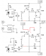
Back to the buffer: if you put 2SK170 as buffer won't it have gain itself or is that where the degeneration comes in?
And I wonder here on the drain of the lower jfet, it shoulnd't have all the voltage from v+ to v- right? So should it be connected to ground there or would that be bad and it would be better to go to v+ but reduce the voltage first with a resistor? Or I'm just confused and it is something else you should do
")
Attachments
Last edited:
if +23 , that means little one goes Dodo very soon
I think +45Vds dynamically is allowed on the 2SK170 but not on max current (Pmax 0,4 W); but at 2 mA for instance (the source resistor is not given) then it should be ok isn't it?
In the schematic of this post, connect the upper buffer exactly like the bottom buffer; as Zen Mod said in an earlier post.semi Silencer

J309/10?Is there available a signal-level, or a low-power SIT to use instead of 2SK170?
A triode is a candidate to make a hybrid; [diyF6H].there are, but really rare.
Thank you for this valuable info.J309/10?
Is there available a signal-level, or a low-power SIT to use instead of 2SK170? Will the updated combination of this SIT buffering R100A behave like a power SIT?
2sk79 is available but expensive.
J309/10?
nope - too high Idss/Vgs , so impossible to squeeze needed value of Rs in 1V25 , which is Vgs for output Jfet
A triode is a candidate to make a hybrid; [diyF6H].
nope in my world , where I refuse to use any part in starvation mode ( either voltage or current)
even if you use low voltage toob , they're inferior to properly implemented small Jfet
So if Rx and Ry are set at 5k ohms, the 2SK170 should only see about half the +/- 23 volts. The current would be about 4.4 mA and dissipation on the jfet should be about .1 watt. What idss should we use?
See attached.
What am I missing? Will this work?
Rush
See attached.
What am I missing? Will this work?
Rush
Attachments
Last edited:
Thank you.2sk79 is available but expensive.
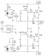
[Ry] calculates to be 270 Ohms. What is the voltage at point 8 of the transformer for the bottom circuit?So if Rx and Ry are set at 5k ohms, the 2SK170 should only see about half the +/- 23 volts. The current would be about 4.4 mA and dissipation on the jfet should be about .1 watt. What idss should we use?
See attached.
What am I missing? Will this work?
Rush
So if Rx and Ry are set at 5k ohms, the 2SK170 should only see about half the +/- 23 volts. The current would be about 4.4 mA and dissipation on the jfet should be about .1 watt. What idss should we use?
See attached.
What am I missing? Will this work?
Rush

you're Dodo in da head almost as Dumbest of Them All - Mighty ZM , itself

you need , say , around 1V2 across both Rx and Ry
then bias seting ports are there to fine tune bias/current through outputs , same as in original scheme
if you put 5K for Rx and Ry , then cuyrrent through buffer Jfets need to be ridiculously small ........ 1V2/5K=240uA
say that you have small Jfets in 10mA range ; then 1V2/10mA=Rx=Ry=120R
put 150 to 180R for starters and enjoy
edit:
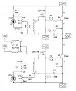
Rx needs to go to output node , not -Ub
Last edited:
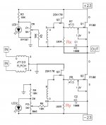
whatever , one pic is worth zilll.......
Thank you that picture.
I know how dumb I am, thanks for pointing that out though, again!
I will try this and see how it sounds, then try some feedback too.
Rush
- Home
- Amplifiers
- Pass Labs
- F6 Amplifier