If you are looking to have a current source (high output impedance) amplifier,
then it would work. If I were doing that, I would say you can eliminate R2
and run the primaries in series from input to ground.

Cool, Ideally I want a current source amp so that would work even better =)
Would it still have about the same high frequency rolloff as a vanilla F6 or would it be limited as if you remove the feedback in a vanilla F6?
Last edited:
Here it is in GIF
Yes, I remember that curve from further back in the thread. It was the main reason why I didn't pursue a current source F6 further then. If I'm not mistaken the reason for it is the transformer, which is what made me have som wishful thinking that it would be possible to easily bypass the transformer since then the feedback could be removed without penalizing the roll off.
Is there any easy ways to extend the bandwidth without adding feedback? I guess you could hook up some resistors and caps to lower the gain before the transformer to something more uniform. In that case then my guesstimate would be a passive line level 50 khz first order highpass shorted by a large resistor would do it.
Last edited:
so nelson watt's new ? working on anything interesting ?
My sheet currently shows about 40 amplifier projects and variations. Most
of them are interesting, and most of them will be constructed for analysis.
Is there any easy ways to extend the bandwidth without adding feedback?
You can give the output devices an active buffer. Usually if I'm looking for a
lot of bandwidth I go active.
My sheet currently shows about 40 amplifier projects and variations. Most
of them are interesting, and most of them will be constructed for analysis.
Slowin down, it seems

You can give the output devices an active buffer. Usually if I'm looking for a
lot of bandwidth I go active.
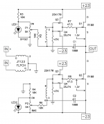
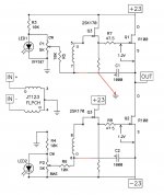
You mean something like this?
Attachments
And disconnect the gate also?
And to further my quest for knowledge I will ask more questions =)
As you saw I just copied the buffer frontend and put it on each side but apparently life isn't that easy =) If the P-fets were removed would there be any issues with DC?
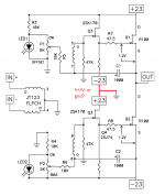
And another design that would be cool to try to build (if it would work that is ) I've seen people use this design to create simple current source amps with chipamps and opamps and they discussed that it might be unstable but the F6 doesn't have that much gain so it might be less of an issue... so I might as well ask your opinion.
Thanks for all the help btw, I see fun amp building in the future...
And to further my quest for knowledge I will ask more questions =)
As you saw I just copied the buffer frontend and put it on each side but apparently life isn't that easy =) If the P-fets were removed would there be any issues with DC?
And another design that would be cool to try to build (if it would work that is
) I've seen people use this design to create simple current source amps with chipamps and opamps and they discussed that it might be unstable but the F6 doesn't have that much gain so it might be less of an issue... so I might as well ask your opinion.Thanks for all the help btw, I see fun amp building in the future...
Attachments
Another question: Would there be any significant distortion performance difference between:
#1 Doing a vanilla no feedback F6 but with series RC to reduce and make gain more uniform.
#2 Doing the after-transformer buffered F6 but reduce the gain globally to the same level as #1.
Or are they more or less equal? If they are equal then It's probably more simple to just add the RC's on the input than to throw in more active circuitry =)
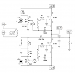
And disconnect the gate also?...
left pic - erase 47K (small Jfet) gate ref. resistors
Ah ok.
And another thing, since I'd love to try and test some and learn I hooked up LTSpice but there seems to be something wrong with my circuit since I'm no expert on the program... so if someone here had and could upload an .asc with dependencies of say a vanilla F6 that works and I could use as base the Ollboll would be very happy =)
And another thing, since I'd love to try and test some and learn I hooked up LTSpice but there seems to be something wrong with my circuit since I'm no expert on the program... so if someone here had and could upload an .asc with dependencies of say a vanilla F6 that works and I could use as base the Ollboll would be very happy =)
And another question: would it be possible to add a small series inductor (or a parallel capacitor) on the secondary side of one half to act as a lowpass? The idea would be to have quasi push-pull, less distortion and more power up to say about 1 khz and from then onwards it would become more and more single ended.
Last edited:
And another question: would it be possible to add a small series inductor (or a parallel capacitor) on the secondary side of one half to act as a lowpass? The idea would be to have quasi push-pull, less distortion and more power up to say about 1 khz and from then onwards it would become more and more single ended.
You are running in several direction. Wish you would settle down.
You have me interested in the buffer version.
Rush
Attachments

- Home
- Amplifiers
- Pass Labs
- F6 Amplifier