I wasn't asking you to look up the values for all FETs you measured, though that should also not be so difficult.
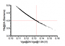
I merely suggested that you could verify your figure of 63mV (or 125mV for that matter) from real measurement.
Bolts for the FETs you'll have to ask Mark.")
Cheers,
Patrick
I merely suggested that you could verify your figure of 63mV (or 125mV for that matter) from real measurement.
Bolts for the FETs you'll have to ask Mark.
Cheers,
Patrick
So, after a log wait, I started again some activities on the F5X. My plan is the following:
1) Proceed channel by channel, right and then left.
2) Get the audio part working, then address the auxiliary functions. I may use a lab PS for this.
So far I completed the cap boards, the R boards, and I have all the passive components mounted on the amp boards.
So far I am addressing only practical/mechanical problems. Of course I have few questions and some findings:
1) Do we have to drill through the hole of the Mosfet to make space for the washer ? I think a 3.5mm bid is needed.
2) The amp boards need to be slightly filed on the side to properly sit between the cap boards.
3) I have the transformer with double primaries: is it worth to put a termistor between the primaries ?
4) For the connection of the DC to the amp boards, I understood that M4 screws to should be used. This can be avoided for the + and -, but not for GND. Any suggestion on where to find copper or brass M4 screws ?
More to come. Thanks,
Davide
Patrick, Nick,
Perhaps one or more of your protection transistors was bad? No ideas otherwise and I cannot make it act like the previous problem in the sim.
Hope it helps,
Dave
I use square pads to designate pin one wherever possible in layouts. For the relay board - pin 1 of the diode is cathode and both pin 1 of the diode and relay were intended to be positive.Dave please cross check.
The protection circuits should not affect the front end current without output devices installed... All measurements in the build article including the front end bias were done with the protection transistors and associated circuits installed.Ok. Removed the bipolar transistors, but also R13 and family.
Perhaps one or more of your protection transistors was bad? No ideas otherwise and I cannot make it act like the previous problem in the sim.
Hope it helps,
Dave
....
4) For the connection of the DC to the amp boards, I understood that M4 screws to should be used. This can be avoided for the + and -, but not for GND. Any suggestion on where to find copper or brass M4 screws ?
...
I got my brass screws from this UK company:
Brass Machine Screws All Types - Page 4
Prices include registered shipping but not VAT.
I have plenty of space......2) The amp boards need to be slightly filed on the side to properly sit between the cap boards.
Are you sure you are not trying to mount the amp boards to the FET holes
An externally hosted image should be here but it was not working when we last tested it.
Shouldn't be like this ?
Davide
> 1) Do we have to drill through the hole of the Mosfet to make space for the washer ? I think a 3.5mm bid is needed.
No. No need at all. Use as they come.
> 2) The amp boards need to be slightly filed on the side to properly sit between the cap boards.
Even though the prototype uses my hand-etched boards, they are stil valid.
Many photos have been posted at the F5X thread.
Please take a look there, or at our website, as heinz1 pointed out.
> 3) I have the transformer with double primaries: is it worth to put a termistor between the primaries ?
What would that do ?
> 4) For the connection of the DC to the amp boards, I understood that M4 screws to should be used.
>This can be avoided for the + and -, but not for GND. Any suggestion on where to find copper or brass M4 screws ?
Almost all suppliers like Farnell, RS, ... have them.
Or something like these :
COPPER SHORT CS_S07 Contact Screw (M4) Metric for Tattoo Machine - Price Per 1 | eBay
Copper Tattoo Machine Parts.
Patrick
The holes are symmetrically spaced so both ways actually "fit".
The parallel orientation that Davide showed however has two downsides: one set of FETs would be mounted at the border of the sink and it would be virtually impossible to adjust the bias trim pots because of the cap banks.
I'm wondering how many, if any, of the batch 1 F5X have been completed
I plan to bias next week-end I think I only miss the speaker binding posts to finish the build.
Cheers,
Nic
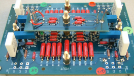
Here is a photo of my board.
I was thinking to use brass standoff's everywhere and connect via solder lugs.
The red wires on the input board are temporarily grounding the inputs. The mute board will go on the 3 (+1 not yet in) wires sticking up on the RH side of the input board. I guess that if I mount this I will not anymore need to ground inputs while biasing
The trim pots are sitting in IC sockets for easy and non-destructive removal later on.
Note that the input board is very effectively blocking easy access to the JFET's so next time I will check front end bias before I mount this board. Not that I think anything is amiss
Attachments
Please kindly read the article about Class A thermal design at Linear Audio.
It is free for download (thank you Jan).
It descirbes in detail how the FETs should be positioned on the heatsink.
The holes as they are are not accidentally there or simply positioned by chance.
There is no other sensible orientation, even if the holes would fit the other way round.
The only reason why they would fit the other way round was a request form the DIYA forum, so that the board will also fit their standard case.
Patrick
Glad to see more builds.
Dave
I've been following Nic's progress carefully, and its been very helpful for my builds. I've basically got everything soldered up except the JFETs, which I still need to match. Hopefully I'll be testing the amp boards and power supply very soon.
I have a feeling there are a few of us who are quietly building away, while following Nic's lead.
Don'tI have a feeling there are a few of us who are quietly building away, while following Nic's lead.
I have zero experience with class A amps - I'm just a careful cell biologist with very little time!>
> 3) I have the transformer with double primaries: is it worth to put a termistor between the primaries ?
What would that do ?
A soft start.
Got the rest, thanks,
D.
You can put the NTC somewhere in series with the primary.
In our schematics we put it between Mains L and the primary.
But in theory anywhere along the way is OK.
You only need to make sure that even if you have a short in the coil, the current still goes through the NTC.
Patrick
In our schematics we put it between Mains L and the primary.
But in theory anywhere along the way is OK.
You only need to make sure that even if you have a short in the coil, the current still goes through the NTC.
Patrick
- Home
- Amplifiers
- Pass Labs
- F5X -- the EUVL Approach - The Build Thread