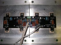
It's ALIVE!
Had an issue with the cascode transistors.
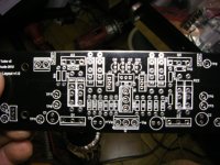
When I first powered the amp with my variac, set on the 2.5 amp fuse, no bias could be set. I was pretty sure where to start looking. Checked the data sheet on the 2SC4793 and sure enough the emitter was not pointed at the JFET source, DOH! Either I don't know how to install them or they are marked wrong on the board. The back side should have the double line right? I believe they are marked wrong on the board, Andy. After trying to fry them (it didn't work) I had to unsolder them (awful job, pulled up 2 traces) and put them back in hoping they were OK, they are OK. The amp pass' a signal too!
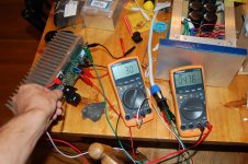
It biased up just fine the second time. Set at .3 VDC.
Being a prototyper I should have checked everything first, but I only checked most things, not everything! DOH again.
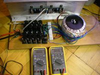
I am running 33.5 VDC on the rails and the heatsink isn't getting that warm, but it has only been on for about 20 minutes and biased at 2.4 amps total, which is all a standard F5 runs at.
Let know if you have any questions.
I fretted over drilling and tapping the heatsinks, but that was an easy job. I drilled the pilot holes all the way through (broke only 1 drill bit when it exited the side of a blade and no tap was broken because I only tapped 1/2 way down the hole). I used fairly short #4 - 40 screws.
I have been thinking about this diode and low bias issue and thinking maybe do away with the diodes altogether. Of course the DIYAUDIO Store has boards that do just that and I'll bet they match the standard spacing (which is too close together, isn't it!)
The proof is in the pudding and I will compare this amy to my standard F5 and see which one sounds the best. This of course will take twice as long as I think it will and somehow cost twice as much.
Thank you Andy for your hard work, I see you have incorporated some of my suggestions already. The terminal blocks need to be able to take 12 gauge wire, currently your BOM has a block that only takes 16 gauge wire, make the speaker output hole larger, so it too could take a 12 gauge wire (there is plenty of room) and mark cascode transistors correctly and you will be good to go.
Rush
Had an issue with the cascode transistors.
When I first powered the amp with my variac, set on the 2.5 amp fuse, no bias could be set. I was pretty sure where to start looking. Checked the data sheet on the 2SC4793 and sure enough the emitter was not pointed at the JFET source, DOH! Either I don't know how to install them or they are marked wrong on the board. The back side should have the double line right? I believe they are marked wrong on the board, Andy. After trying to fry them (it didn't work) I had to unsolder them (awful job, pulled up 2 traces) and put them back in hoping they were OK, they are OK. The amp pass' a signal too!
It biased up just fine the second time. Set at .3 VDC.
Being a prototyper I should have checked everything first, but I only checked most things, not everything! DOH again.
I am running 33.5 VDC on the rails and the heatsink isn't getting that warm, but it has only been on for about 20 minutes and biased at 2.4 amps total, which is all a standard F5 runs at.
Let know if you have any questions.
I fretted over drilling and tapping the heatsinks, but that was an easy job. I drilled the pilot holes all the way through (broke only 1 drill bit when it exited the side of a blade and no tap was broken because I only tapped 1/2 way down the hole). I used fairly short #4 - 40 screws.
I have been thinking about this diode and low bias issue and thinking maybe do away with the diodes altogether. Of course the DIYAUDIO Store has boards that do just that and I'll bet they match the standard spacing (which is too close together, isn't it!)
The proof is in the pudding and I will compare this amy to my standard F5 and see which one sounds the best. This of course will take twice as long as I think it will and somehow cost twice as much.
Thank you Andy for your hard work, I see you have incorporated some of my suggestions already. The terminal blocks need to be able to take 12 gauge wire, currently your BOM has a block that only takes 16 gauge wire, make the speaker output hole larger, so it too could take a 12 gauge wire (there is plenty of room) and mark cascode transistors correctly and you will be good to go.
Rush
Attachments
Last edited:
Put the diodes in and fire it up and just see hoe hot they get with just a small hearsink attached. Mine didnt eben get real warm in free air with no heatsink. If you consider their very poor ability to dissipate heat into free air with no heatsink, then you realize they are not putting out hardly any heat.
It could be argued, that if you want to hear the effects of having the diodes, you have a better chance of doing so with less pairs, where it is more likely they will push beyond their bias point. This assuming you are not driving big or inefficient floorstanders. In that case you will probably be using them regularly.
It could be argued, that if you want to hear the effects of having the diodes, you have a better chance of doing so with less pairs, where it is more likely they will push beyond their bias point. This assuming you are not driving big or inefficient floorstanders. In that case you will probably be using them regularly.
Last edited:
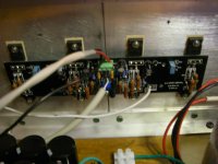
At idle, with diodes on cheapo 25C/W+ heatsinks, I can get the bias up to almost 1A (.485 across Rs and diodes)before they start to want to jog a little. This is with the little heatsink sitting at 31-32C. All the little heatsink is doing is keeping it from having to dissipate in free air, not much more. The large heatsink are at 42C roughly. I will mount the next version with diode on main sink, which will raise the temp on it and we will see how that affects bias point. Next I will run a signal through it into 2OHM load to push it and see what happens.
Attachments
Biasing the output stage to the the point and beyond where the diodes are passing just seems wrong to me.
My feeling is that the diodes should only pass when the speaker demands extreme currents and that should only happen when extreme transients are being processing. NOT when the amplifier is quiescent and just bias current flowing, i.e. none to the speaker load.
My feeling is that the diodes should only pass when the speaker demands extreme currents and that should only happen when extreme transients are being processing. NOT when the amplifier is quiescent and just bias current flowing, i.e. none to the speaker load.
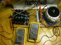
I am just seeing about general settings here. when i run it with a load, I will have it set much lower. I will try it at .450 in open air. I am trying to push then to see when and at what temperature they will react at. After open air test, they will go in a case. BTW, I had them over 1A bias and stable, in open air, but that is just playing with fire.
Andrew, they are not biased beyond their passing or they would take off, correct. I am still below threshold, although on very shaky legs.
Andrew, they are not biased beyond their passing or they would take off, correct. I am still below threshold, although on very shaky legs.
Last edited:
Little note for perspective builders. The idss value of the jfets is important with things set as they are in the article. I fired up the second channel and couldnt get bias beyond a certain point. Problem was low idss k170. I replaced it with 9.2mA and all was fine. If you have only low idss jfets, you might have to consider lower Rs than 10 in ordr to have enough current to bias output fets. You could increase 5K pot, but this is less effective, from what i remember. My vdrp across jfet sorce resistors is 50mV for sj74 and 61mv for N channel.
Little note for perspective builders. The idss value of the jfets is important with things set as they are in the article. I fired up the second channel and couldnt get bias beyond a certain point. Problem was low idss k170. I replaced it with 9.2mA and all was fine. If you have only low idss jfets, you might have to consider lower Rs than 10 in ordr to have enough current to bias output fets. You could increase 5K pot, but this is less effective, from what i remember. My vdrp across jfet sorce resistors is 50mV for sj74 and 61mv for N channel.
Yep, I did 10K pots since I have a shortage of JFETs. Or change 1K to 2.2K R5-R6. Gives a little more breathing room. I believe this will likely affect cascade building people more.
hola guys,
correct me if I'm wrong, but the MUR3020 has a V forward of 1.05V@25c and .85V@150c. So at idle the voltage drop across the source resistors is somewhere between 450mv to 600mv and at that voltage the MUR3020 should not conduct till the amp is rocking at near full tilt. The purpose being to allow the outputs to swing closer to the rails. At least that was my understanding.
Regards, El
This is a very important error, Eyoung. The part spec'd by Nelson is the Mur3020W and is linked below
http://www.vishay.com/docs/94080/mur3020w.pdf
Very easy mistake to make. Fortunately anyone who got this part would not suffer any negative consequences, as it indeed conducts much later than the "w" designated part.
Tea is right about being able to tweak circuit for other idss fets, but doing so does change parameters such as FE gain. How much this affect things, I do not know. I dont thin it matters whether it is cascode version or not. Low idss fets should have same effect no matter the version.
So please look over UKToecutter's boards here and check for errors. Otherwise they're ready to go. He has decided to have the boards available in the store instead of sending them out himself.
http://www.diyaudio.com/forums/pass-labs/206756-f5-turbo-circuit-boards-134.html#post3004341
Here is his spreadsheet for ordering boards.
https://docs.google.com/a/crozone.c...UAE2eGAZdExKMzBJNEluSTZ1LVg2LVJnN2xyeUE#gid=0
Problem is that the boards are a bit different now, but to me it seems easy to figure out what people want. These are the assumptions I made:
First categories are Input Boards and Balanced Input Boards. It would seem that they are now the same thing, ie now a double board with the scored center line?
So it seems we could combine the categories, and for each 2 old input boards requested put 1 new Input Bd. And for each balanced board requested 1 new Input Bd.
Next category is Output Boards.
the old Output Bds worked for both P and N channels. If someone ordered 2 then its pretty safe to assume that they wanted one N and one P? I note that all the orders are for an even number, so I think its safe to assume that they want half P and half N.
Hmmmm? Combo boards? And Single boards? Now that we have boards with only 2 positions, maybe we don't need singles? Maybe just cut the number in half , then make half P and half N?
I think we'll create a New Board Request spreadsheet. And leave the original, and ask you people to confirm that what you put on the NBR spreadsheet is correct, and that you're still interested. Its been a while so confirmation of interest is good..
We'll get to it soon
Mark
Last edited:
hola guys, correct me if I'm wrong, but the MUR3020 has a V forward of 1.05V@25c and .85V@150c.
Hola,
at 15A, homes.
For a higher Vf at 0.1A, see the OnSemi MUR3040/60 PTG, not as linear though.
(hope you gents realise that a diode is a semiconductor)
Last edited:
So please look over UKToecutter's boards here and check for errors. Otherwise they're ready to go. He has decided to have the boards available in the store instead of sending them out himself.
http://www.diyaudio.com/forums/pass-labs/206756-f5-turbo-circuit-boards-134.html#post3004341
Here is his spreadsheet for ordering boards.
https://docs.google.com/a/crozone.c...UAE2eGAZdExKMzBJNEluSTZ1LVg2LVJnN2xyeUE#gid=0
Problem is that the boards are a bit different now, but to me it seems easy to figure out what people want. These are the assumptions I made:
If we are looking down on the boards in the linked photo, as far as I can see Q5 and Q6 are still wrong. The double line is on the wrong side. The Emitter should point to the JFET's Drain and they don't. I had to draw them on a piece paper and turn it upside down to make sure.
I put them in according to the graphic on the board and had to unsolder them in the prototype V2 boards and turn them around.
Secondly there are not enough ground holes. The link hole has no open ground hole to link to. Input ground wire, power ground wire, Link to where? double wires in one hole?
One more thing, in this new version, where is the hole for the speaker output? All the O/P holes in the input board are full, you wouldn't want to take the speaker wire from the N or P boards. You should connect the speaker wire to where the N and P boards connect together, at the input board, right?.
Rush
Last edited:
What do you mean?...........they are not biased beyond their passing or they would take off,.......
Tea is right about being able to tweak circuit for other idss fets, but doing so does change parameters such as FE gain. How much this affect things, I do not know. I dont thin it matters whether it is cascode version or not. Low idss fets should have same effect no matter the version.
So we should be recommending 9-10ma matches based on our experiences is what I take out of it. Easier setting with the pots.
Someone is RUSH
") ing me some JFETs up generously to see how they play in my F5T boards.
ing me some JFETs up generously to see how they play in my F5T boards.My bad. Mental fart. Lost sight of the fact that the fet still controls current throught the circuit.What do you mean?
So we should be recommending 9-10ma matches based on our experiences is what I take out of it. Easier setting with the pots.
Someone is RUSH
I would agree and i think this agrres with the numbers you are getting from the original article. I have even considered J309/271 in the cascode version.
- Status
- This old topic is closed. If you want to reopen this topic, contact a moderator using the "Report Post" button.
- Home
- Amplifiers
- Pass Labs
- F5 Turbo Circuit Boards