I guess your right. My feelings are that few will operate at those power levels. Even if you need it, the increased temperature willcontribute to heatsink temperature, still causing the change you suggest. More than likely, the changes will be instantaneous vs constant. I will try one channel each way and track temperature. Consider two amps through every diode in V3. You have only 1W of dissipation per diode,but 16A of available current to the load. Perhaps some will need more power, but it seems hard to imagine. This is a benefit of the increased output pairs IMO. More intial bias heat, but not as much fluctuation during playback as with lesser quantities. As always i could be viewing this in incorrect terms
Excellent solution......... try solder an extra resistor on top of existing one that will give you 0.33 ohms........
Even a fourth might work. But the disadvantage of source resistor set to 0r25 is that there may not be sufficient thermal stability for the output device.
Excellent solution.
Even a fourth might work. But the disadvantage of source resistor set to 0r25 is that there may not be sufficient thermal stability for the output device.
Closely matched devices will help in this regard, correct?
No.
Pass chose 0r6 or thereby.
The Vds and Rs are closely linked for thermal stability.
Going lower on Vds will allow lower Rs.
Euvl's F5x used this, +-16Vdc supplies and Rs= 0r22
But the F5T is intended generally for higher voltage and this may require a higher Rs than 0r22.
Pass chose 0r6 or thereby.
The Vds and Rs are closely linked for thermal stability.
Going lower on Vds will allow lower Rs.
Euvl's F5x used this, +-16Vdc supplies and Rs= 0r22
But the F5T is intended generally for higher voltage and this may require a higher Rs than 0r22.
Am I missing something?
What you are missing is that the Turd-O is a 1-side sliding bias amp.
The static bias value only delivers part of the Class A output current, by the time there's 0.6V across the source resistors (and next to 0V on the other side), current through the diode could be at 1A.
For a 2-pair output stage, that would amount to 4.4A total, >50% over your 50W mark.
To estimate what the diode current would be at 0.3Vf, for other than datasheet temperatures, extrapolate the If/Vf graph curves (in the order of 10mA at 50-55C).
An accurate measurement value will be equal or lower, not higher (S-curve).
I still do not believe that adding the bypass diodes while keeping the bias voltage at 590mV will not compromise the performance of the amplifier.
I still believe the diodes should only pass when extra current is demanded. This can only happen if the bias voltage is reduced to substantially below the usual 590mV.
If one requires 1.3A of bias (of a standard F5 output stage) and expects the bypass diode to pass near zero current then the bias voltage needs to be ~ 400mV. This would require the source resistor to be reduced to ~0r3
I do not know if the F5 would work well with Rs=0r3.
That's why I put out a call for advice on what to do with the F5T biasing.
I am still waiting. Where have all the experts gone?
Are you saying that Rs value is related to rail voltage. Could you explain further? I thought it was mainly for stability against current hogging and linearization.
buzzforb, I beleive you are mostly correct. The Rs is based on the Vgs and the parts own R. With current and temp the linearity and bias point will change. The Rs has a portion of the total V gate-gnd (in Common Source) and bias through it and the voltage drop across it. The Rs has more stability and it's own temp coefficient. When these changes in temp and current do happen to the FET, the resistor imparts stability to the circuit. The bigger the resistor, the more it swamps the FETs ability to shift the circuit parametors non liearly. But, the more it reduces gain also. I have seen where designers of some type of circuits just choose an R that drops about 20-30% of Vgs. We would proabaly be around 15% with our typical Rs's?
Patrick has chosen a FET with roughly 1/2 the Vgs of the original F5 deices. Bias current etc. being roughly equal would support an Rs being roughly 1/2 the value
Increasing bias current would support the use of even lower Rs for the same effects. Just my 2c
Last edited:
What numbers am I looking for?Tea,
What numbers did you get?
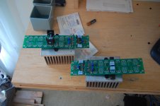
I hope to spend more time getting mini V3 version with mini-Diode heatsinks, and the V2 version with direct attached diodes to heatsinks in comparison. Going to use some low hz sine wave loops from old test disk to see what results. That's the plan anyway. The wife suddenly wants to change all that.
Many of N.P.s articles discuss Rs size directly related to bias through the device. Useing more devices with less bias he will suggest maybe a 1 ohm rather than a .47. More than an amp bias he might suggest less than a .47 ohm Rs. I'm not saying there is no Vds effect better/worse regarding Rs big/small. But, Rs significantly effects other parameters of the circuit with only a minute change in Vds?
Regarding DC/Thermal stability, when a gate voltage refrenced to ground is applied to the FET, the FETs tempco becomes a significant variable in stability. A large source R can overcome the significant Vgs shift with temp vs. the applied gate to ground voltage and improve stability.
I beleive Patrick has mentioned that the Fuku Rs we are using in the F5X have a TempCo that may be the opposite of the FET offering some automated control assistance???
Many of N.P.s articles discuss Rs size directly related to bias through the device. Useing more devices with less bias he will suggest maybe a 1 ohm rather than a .47. More than an amp bias he might suggest less than a .47 ohm Rs. I'm not saying there is no Vds effect better/worse regarding Rs big/small. But, Rs significantly effects other parameters of the circuit with only a minute change in Vds?
Regarding DC/Thermal stability, when a gate voltage refrenced to ground is applied to the FET, the FETs tempco becomes a significant variable in stability. A large source R can overcome the significant Vgs shift with temp vs. the applied gate to ground voltage and improve stability.
I beleive Patrick has mentioned that the Fuku Rs we are using in the F5X have a TempCo that may be the opposite of the FET offering some automated control assistance???
This is the theory i was going on. The introduction of the diode creates another level of complexity as it it adds its on dynamic characterstics.
Speaking of automated control assistance, adding a low value power resistor in series with the diode. (a relic pot smoker would dream of high current silistors)
This is either a hint or an older joke than my internal reference material, although some of the statement was relevant, personally.
Here is how I am going to test them. I amusing small sinks intentionally, so that i can make sure the heat is high. One will have diodes mounted to sink, the other freestanding. I will drive parallel 4 ohm speakers to give it a nice tough load. If it gets too hot, I'll put them on larger sinks.
Attachments
...........I do not know if the F5 would work well with Rs=0r3.
That's why I put out a call for advice on what to do with the F5T biasing.
I am still waiting. Where have all the experts gone?
That was a genuine question. I am asking.........How do you suggest we arrive at this ratio?
- Status
- This old topic is closed. If you want to reopen this topic, contact a moderator using the "Report Post" button.
- Home
- Amplifiers
- Pass Labs
- F5 Turbo Circuit Boards