Guys, as someone who's DIY for cases, it's really not that difficult.
The on-going debate is "right on the mark". For an amp with two (left-side and right-side) heatsinks, it's easiest to allow the heatsink dimensions determine the size (depth and height) of the case. Once the heatsink dimensions are known, aluminum sheet/plate can be cut for the base plate, top plate, rear apron and front panel (four pieces). A metal shop with a good metal shear can cut these to size, only for the cost of materials and a "cut charge". We all should be able to drill the holes for the "small stuff" like binding posts, RCA jacks, panel switches. (Admitedly, drilling and tapping blind machine threads into an expensive heatsink can be a little nerve-racking.) A good "water jet" metal shop can cut larger or more exotic shapes like chassis vents, IEC outlet holes, fans, etc, etc. Other shops (like Front Panel Express) can do engraving, if you desire....and shops that do powder coat or anodizing should not be that far away (or are accessible through UPS, FEDEX, and other mail services).
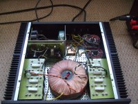
My amp cases are home made, typically using 1/8" or 3/16" T-6061 aluminum.
No reason why you can't DIY a case that looks as good as a commerical unit, and to the specific design you want.
If we GB PCBs, components, transformers, and cases--then aren't we really just putting a "kit" together? (...... in sucn an instance, aren't we becoming KiyAudio'ers, and not DIY'ers?....)
The on-going debate is "right on the mark". For an amp with two (left-side and right-side) heatsinks, it's easiest to allow the heatsink dimensions determine the size (depth and height) of the case. Once the heatsink dimensions are known, aluminum sheet/plate can be cut for the base plate, top plate, rear apron and front panel (four pieces). A metal shop with a good metal shear can cut these to size, only for the cost of materials and a "cut charge". We all should be able to drill the holes for the "small stuff" like binding posts, RCA jacks, panel switches. (Admitedly, drilling and tapping blind machine threads into an expensive heatsink can be a little nerve-racking.) A good "water jet" metal shop can cut larger or more exotic shapes like chassis vents, IEC outlet holes, fans, etc, etc. Other shops (like Front Panel Express) can do engraving, if you desire....and shops that do powder coat or anodizing should not be that far away (or are accessible through UPS, FEDEX, and other mail services).
My amp cases are home made, typically using 1/8" or 3/16" T-6061 aluminum.
No reason why you can't DIY a case that looks as good as a commerical unit, and to the specific design you want.
If we GB PCBs, components, transformers, and cases--then aren't we really just putting a "kit" together? (...... in sucn an instance, aren't we becoming KiyAudio'ers, and not DIY'ers?....)
Attachments
The amp does not stay in class A when the diodes are active unless the bias current is greater than 1/2 the current at which the diodes are active.
Now that is what i call an aenigma.
And which current would that be ?

simple and easy
s = source resistor
d = common cathode diode
I = current
V= voltage drop between rail and source
It = I(total) = Is +Id
Vs = Rs * Is
Vd = Vdrop = Rd * Id (Rd = dV/dI)
No1 condition : V = Vs = Vd
=> Rs * Is = Rd * Id = Vd (Vd = 0.5 * Is)
=> Rs/Rd = Id/Is
=> Rd = 0.5 (It/Id - 1)
If It goes up, Vd goes up. (or as Vd goes up, It goes up)
When Vd goes up, Rd drops, Id goes up => Rs/Rd goes down, Id/Is goes down.
You should have driven this car : Variomatic - Wikipedia, the free encyclopedia
Between source resistor only and full diode open, there's a smooth transition phase with proper diodes.
Which is what the nfb can track.
[equivalent resistance diode : dV/dI. Between 0.8V and 0.5V : (0.8V -0.5V)/10 = 0.3/10 = 0.03 Ohm ]
Last edited:
with Fets you get an output stage that will deliver more Class A power at a given bias figure due to the square law character of the Fets."
Square law character means that one goes open further than the other closes.
square 2 = 4
square root 2 = 1.41
source resistors linearise.
s = source resistor
d = common cathode diode
I = current
V= voltage drop between rail and source
It = I(total) = Is +Id
Vs = Rs * Is
Vd = Vdrop = Rd * Id (Rd = dV/dI)
No1 condition : V = Vs = Vd
=> Rs * Is = Rd * Id = Vd (Vd = 0.5 * Is)
=> Rs/Rd = Id/Is
=> Rd = 0.5 (It/Id - 1)
If It goes up, Vd goes up. (or as Vd goes up, It goes up)
When Vd goes up, Rd drops, Id goes up => Rs/Rd goes down, Id/Is goes down.
You should have driven this car : Variomatic - Wikipedia, the free encyclopedia
Between source resistor only and full diode open, there's a smooth transition phase with proper diodes.
Which is what the nfb can track.
[equivalent resistance diode : dV/dI. Between 0.8V and 0.5V : (0.8V -0.5V)/10 = 0.3/10 = 0.03 Ohm ]
Dutchie ....So with diode the best way ...? if so why not this way before ...?
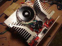
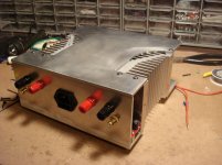
Yes I agree that the units has a number of parts that are heavy, the only thing i wont have is the chokes,
I got a couple of kilos (that is how they sell it) of 2mm cooper made a cuple of coils an went that way next time I will try same again but wind them as comon mode (1 coil 2 wires side by side)
work quite well as CRCLC
Attachments
Last edited:
So still high bias rules the day.
So I go back to my Balanced Cascoded F5. 16V rails and high bias. Lots of Class A. I'm not sure why one would chase high rail voltages instead of high current.
The amp does not stay in class A when the diodes are active unless the bias current is greater than 1/2 the current at which the diodes are active.
If now i understand "more classA for a given bias" I still do not get what you are stating.
why not this way
Push-Pull Class AB is a way to get more power per lb, also with tricks as (feed-forward) EC or TMC, is it the best way or a practical way ?
For me just fun, i get bored easily.
Push-Pull Class AB is a way to get more power per lb, also with tricks as (feed-forward) EC or TMC, is it the best way or a practical way ?
For me just fun, i get bored easily.
Dutchie ,
i'm going for 600-800b watts @1 ohm(28volt trans) and will run as much class-a bias as necessary for best sound. As you i'm using 50 watts/8ohm class-a to start with , if more sound better, then up, if going lower still sounds good then lower ...
Since I also plan to use somtimes on 8-4 ohm speakers 50 watt class-a might be the magic number ...
Should i keep the diodes ...?
Last edited:
So I go back to my Balanced Cascoded F5. 16V rails and high bias. Lots of Class A. I'm not sure why one would chase high rail voltages instead of high current.
 I was going to say that 16V rails is for girlies but then you get offended so I will not say that.
Supose one listen to music and at times this being a very ramdom thing your amplyfier may be ask to put out loads of volts like more than 12 V rms in my case
with 16 V rails in my case it will be clipping with 36 V rails it will not (I hope).
Supose I decide not only to listen to music but also try to listen to classicall music with much more dinamic range than normal.
36 V rails look a bit girlish as well.
Yes agree no point chasing hi voltagge rails if one is not prepared to spend a lot of dosh and effort to suply the hi current as well.
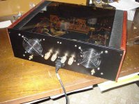
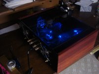
Guys, as someone who's DIY for cases, it's really not that difficult.
If we GB PCBs, components, transformers, and cases--then aren't we really just putting a "kit" together? (...... in sucn an instance, aren't we becoming KiyAudio'ers, and not DIY'ers?....)
Absolutley 100% agree
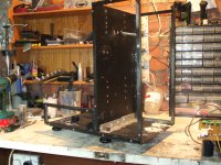
Stick 4 legs on heat sink and wrap the rest in wire mesh for best air circulation
As she just see the front stick a nice piece of granite tile on it.
Done
and if you want to make different thing just take apart and trim to size
Attachments
Supose one listen to music and at times this being a very ramdom thing your amplyfier may be ask to put out loads of volts like more than 12 V rms in my case
with 16 V rails in my case it will be clipping with 36 V rails it will not (I hope).
Supose I decide not only to listen to music but also try to listen to classicall music with much more dinamic range than normal.
36 V rails look a bit girlish as well.
Yes agree no point chasing hi voltagge rails if one is not prepared to spend a lot of dosh and effort to suply the hi current as well.
In a balanced amp, the 16V rails produce 32V swings. That should be more than enough for your listening. You also get all Class A (not AB). Maybe you should rethink your project.
Nyc1 said it, but it is not accurate.
Each half of the balanced amplifier sees half the total load impedance. This effective lower load impedance uses up the ClassA current capability. This is equivalent to saying that the F5T transitions over to ClassAB earlier than a single ended Push Pull ClassA amplifier.
16V Vcc does not permit 16Vpk output at the speaker.
A typical F5 output stage is likely to achieve ~ 4V less than Vcc at the speaker terminals.
Using a balanced pair running on +-16Vdc is likely to result in 24Vpp to 25Vpp at the speaker terminals. Certainly not 32Vpp, not even into a 100k test load.
If 36Vpp at the speaker terminals is required, then expect to use supply rails of ~+-22Vdc
Last edited:
Nah 32 V swing not hardly enoug especialy as with 16 rails you could use only 14 volts as F5 start clipping at 2 volts from rails. so you only get 28 V peak to peak
But just thinking you got same to sell so any comment against sisssy voltagge get stumped
So you shuld refink the limitation of IKEA pretty preetty box with very poor heat dissipation impose and leave free thinking general population decide what best for them.
My room my speakers my ear much different from yours
But just thinking you got same to sell so any comment against sisssy voltagge get stumpedSo you shuld refink the limitation of IKEA pretty preetty box with very poor heat dissipation impose and leave free thinking general population decide what best for them.
My room my speakers my ear much different from yours
Last edited:
I bet you're really popular with your neighbours...
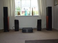
What are those speakers?
Never have any problem with neighbours
just changed job 12 hours shift 4 on 4 off just so I could play propper
Love it when I am home during week days and the rest of road is empty.
Actualy neigbours love me a lot loads of could you fix my light bulb and the string bit in the shower does not work (do them for free)
That stop them moaning about 4 in pipe in the car.
And 3 doors down actualy came over saiing how nice It sounds
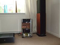
The speakers are Polk LS15i prety nice 3D stage presentation (mean realy goooooood)
Against points
Bit to much bas (but that in my room)
Low impedence 4 Homs Nominal and only 87dB (that why I need volts and current)
and post sale support at least in UK is realy realy CRAAAAAAAAAP
and this main important part IMO, so would I buy again maybe not
Cremonas quite same sort to make comparison. (saving up for them)
Saiing al that a Krell integrated (400i if I remember) sounded realy sqack
F5 much better (could not realy believe myself how good it is)
with very minor correction all the above is OK.For 100W into 8 Ohms using P=I^2R
100/8 = 12.5 therefore I = ~3.536A
P=IV so V=100/3.536 = 28.28V
but you are working with ac voltage.
For an equivalent heating effect (power) to the DC equations shown, you must add ac to all your currents and voltages.
From the Vac and Iac you can determine the peak of a sinusoidal waveform using the sqrt(2) factor.
100W into 8r0 requires 40Vpk and 5Apk.
This requires the F5 to output 80Vpp at the speaker terminals and if the load is truly resistive then 5Apk to flow around the test load circuit.
F5 running on +-44Vdc and biased to ~2.6Adc will stay in ClassA all the way to 5Apk.
Useful shortcut to remember.
50W into 8r0 is equivalent to 20Vac
100W into 8r0 is equivalent to 40Vpk
Halving or doubling those voltages, changes the powers by a factor of 4times (+-6dB)
Last edited:
- Status
- This old topic is closed. If you want to reopen this topic, contact a moderator using the "Report Post" button.
- Home
- Amplifiers
- Pass Labs
- F5 Turbo Circuit Boards