
So......
Where does this leave us in terms of PCB layout?
Are we back to the drawing board?
Nope....fantastic boards, but since this is a beast those wishing to stretch V3 to full class A will need other option like split input and power boards...like BA2/BA3....
Which is easy to do with this layout ...just clip the two ends of the board and voila....split input board.
yes they are..total agreement.
People entertaining the idea that a 250mm deep stereo V3 is possible...even with forced cooling it would be a task and then some.
V3 is a BEAST no doubt about it.
i'm using 250mm x 120mm x 73mm heatsinks for a JLH 10W (pr. ch.) and 500x150x73mm for F5 on steroids
Nope....fantastic boards, but since this is a beast those wishing to stretch V3 to full class A will need other option like split input and power boards...like BA2/BA3....
Which is easy to do with this layout ...just clip the two ends of the board and voila....split input board.
even easyer to clip them at the drawing bord
yes they are
My F5 is pretty compact, like Firstwatt, 300cm deep /12cm high /8cm fins
runs at around 50ºC in Lisbon Summer.
Standard power rails !
even easyer to clip them at the drawing bord
...well yeah that is what i meant.
250mm x 120mm x 73mm heatsinks for a JLH 10W (pr. ch.)
Me have Aleph-J monaurals with 400mm heatsinks on the left and right side.
Eeh, but just a hair over 2.5" high !

My F5 is pretty compact, like Firstwatt, 300cm deep /12cm high /8cm fins
runs at around 50ºC in Lisbon Summer.
Standard power rails !
my F5 will run å liiiitle higher bias
almost dobble it's dual outputsMe have Aleph-J monaurals with 400mm heatsinks on the left and right side.
Eeh, but just a hair over 2.5" high !
hehe
sounds like modu's dissepante 2U 400mmWhere does this leave us in terms of PCB layout?
Are we back to the drawing board?
Would a "Driver board" and a pair of "Output boards" make things more flexible? And easier to accommodate monoblocks and stereo chassis? No doubt. But it also adds a bunch of cost...
What about having a board with seams and the ability to break away the outputs? Like the BrianGT Aleph board. This is more complicated than I thought at first glance because the thermistor circuit need to travel with the outputs, but I think it could be accommodated into your board with a minimum of fuss.
Measured Heatsink Performance
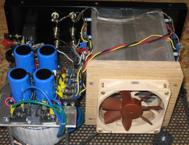
I made some temperature measurements of my F5 amplifier which uses 7" long HeatsinkUSA E007 heatsink. As shown in F5 Power Amplifier post 10205 http://www.diyaudio.com/forums/pass-labs/121228-f5-power-amplifier-1021.html#post2453420, the heasinks consists of a heat tunnel produced by connecting halves of the E007 heatsink. The heatsink is cooled with a Noctua NF-S12-B fan. The F5 amplifier has a standard bias current of 1.3A, resulting in about 62W per channel power dissipation.
Here are the temperature measurements:
22C Inlet air temperature
32C Heatsink near inlet and near mosfet
36C Heatsink near exhaust and near mosfet
14C/62W => R = .226 C/W for 1/2 E007
A full E007 would provide R = .113 which is enough for the F5-Turbo at 180 watts dissipation.
sill.it does't solv the problem for those that don't want to use fans
Would a "Driver board" and a pair of "Output boards" make things more flexible? And easier to accommodate monoblocks and stereo chassis? No doubt. But it also adds a bunch of cost...
A universal board set would have greater appeal to more builders and cost less. As far as the total cost to build the amp, it's not gonna be cheap to build a high power class A amp anyway. So what's a bit more expense to do it right?
Also the dissipation will vary dependant on what each individual chooses for his supply rails and how 'hot' he bias's.
Me, I'm only looking for about 100W into 8 Ohms so I will be conservative with my AC supply.
Only 100 watt?
It's a PP class-A amp, so according to THIS it's around 40% efficient. 100 watts output will need about 250 watts of dissipation... Per channel...
Although we don't have a direct quote to work from, let's see what Papa says about this, from the original F5 manual; bold is mine.
Nelson Pass said:F5 Heat Sinking
At 1.3 amps per channel, you will see idle heat dissipation of 62 watts. To keep the temperature rise of the heat sink to 20 deg C. above the ambient temperature, you will want a heat sink rated at about .6 deg C./watt for each transistor. An example of this would be a chunk of finned aluminum, with a series of 2” fins attached to an 8” by 6” base. You will need two per channel.
Inferring from this it's a safe bet to say that his sample heatsink, which is 48 square inches (120 square centimeters) is required for every transistor!!
So, our worst-case scenario F5 v3, biased fully class-A, with 8 transistors per channel, and then 16 in a stereo chassis, you come up with 768in^2, or 5.3 square feet (1.6 square meters) of heatsink required.
So, a normal-looking, flat back heatsink, convection cooled is going to be staggeringly large. The heatsink profile will need to be much more complex. And probably fan-cooled.
Somebody please correct me if my back of the napkin calculations are incorrect.
Last edited:
Only 100 watt?
It's a class-A amp, so it's basically 25% efficient. 100 watts output will need 400 watts of dissipation. Although we don't have a dorect quote to work from, let's see what Papa says about this, from the original F5 manual; bold is mine.
Inferring from this it's a safe bet to say that his sample heatsink, which is 48 square inches (120 square centimeters) is required for every transistor!!
So, our worst-case scenario F5 v3 with 8 transistors per channel, and then 16 in a stereo chassis, you come up with 768in^2, or 5.3 square feet (1.6 square meters) of heatsink required.
So, a normal-looking, flat back heatsink, convection cooled is going to be staggeringly large. The heatsink profile will need to be much more complex.
Somebody please correct me if my back of the napkin calculations are incorrect.
and you wont get the heat spread over the sinks with the outputs mounted on the PCB
It's a class-A amp, so it's basically 25% efficient.
Wrong
split PCB's will almost be a must for V3 at full power without forced cooling.
V2 can be build as stereo amp. but V3 has to be monoblocks.
monoblocks will be cheeper to, when it comes to heatsinks.
How must building two chassis be cheaper than one ......
100W continuous output power in 8 Ohm means 40V peak.
Add 5V for losses : 45V rails.
100W Class A in 8 Ohm means 2.5A bias.
With 45V rails : 225W output stage dissipation, of which the heatsinks will have to swallow ~220W.
But why full Class A ?
Bias to 25W in 8, the rest in AB : 110W for the heatsinks !
Still desire full Class A : go fan blown or build yourself a huge stereo power amp.
(me balanced X-files, 50W Class A, rest AB, 2 boards on 1 heatsink tunnel, with those pretty Noctua fans that Ihquam posted)
Precisely JV ...
Split boards mean wires , mono blocs mean additional cost .........
How must building two chassis be cheaper than one ......
Precisely JV ...
Split boards mean wires , mono blocs mean additional cost .........
you must have about dobble amount of heatsinks for a stereoamp then 2 monoblocks. lower heatsinks are more efficent than tall ones.
- Status
- This old topic is closed. If you want to reopen this topic, contact a moderator using the "Report Post" button.
- Home
- Amplifiers
- Pass Labs
- F5 Turbo Circuit Boards