The bipolar devices are generic, so substitutions for them are not
a problem.
The JFET inputs should be as close to 2SK170, LSK170, 2SK370 and
2SJ74, 2SJ108 as possible. You might ask at the Solid State forum for
recommendations for replacements. Mostly you need the high
transconductance figure.
The IRF240 and IRF9240 will work, but the IR versions of the 9240
have the "P channel distortion" which has been discussed in this
forum and elsewhere, and so will not have as low a distortion figure.
The IRF250's and IRF9250'swill also work, but they have higher
capacitance, and might require some compensation, as well as
having the P channel distortion.
This Ebay seller has 8.5" heat sinks in lengths up to 73.5"
http://cgi.ebay.com/HEATSINK-ALUMIN...ryZ29402QQssPageNameZWDVWQQrdZ1QQcmdZViewItem
What length would be good for each channel of the F5 to constitute a "really big" heat sink without any "stinkin calculations"?
http://cgi.ebay.com/HEATSINK-ALUMIN...ryZ29402QQssPageNameZWDVWQQrdZ1QQcmdZViewItem
What length would be good for each channel of the F5 to constitute a "really big" heat sink without any "stinkin calculations"?
HS
I find 18" is an great depth to get a good layout, then go a foot across.
vonfilm said:This Ebay seller has 8.5" heat sinks in lengths up to 73.5"
http://cgi.ebay.com/HEATSINK-ALUMIN...ryZ29402QQssPageNameZWDVWQQrdZ1QQcmdZViewItem
What length would be good for each channel of the F5 to constitute a "really big" heat sink without any "stinkin calculations"?
I find 18" is an great depth to get a good layout, then go a foot across.
It would be best to do a search on known heat sink profiles. I would prefer metric dimensions for making comparisons but from what I calculated, this one is somewhat smaller than my Fischer SK47 profile. Mine has 10mm thick body, 40mm full depth and I bought two pieces of 1 meter for having fun. With one meter sliced into four, the calculation added up 2x250mm height (length) for about 2x75Watts. As I'm about to use those for Aleph 5 which has about 150 Watts per channel, I'll have to go with 4 sections, that is, use up one whole meter block. With somewhat thinner and less like Fischer SK42 (not the one on ebay) with 100mm (roughly 4") height it's 1.0K/W and I would say roughly, 250mm (10") height would be just about enough. Per channel. The ones on ebay appear to be just between the two, so if you can afford to buy two 10" sections, that would allow the trannies to warm up most likely as much as they should, but not over that. Adding more to height would require a really tall box. In case you prefer without stinking calculations, then just measure how much height you need to nicely tuck in the filtering capacitore and buy four sections of that height. Take care not to go under that required 10" per channel. That's approximately if you don't want to calculate.
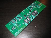
F5 PCB's
Hi Roumen,
The boards are here, I've built up and tested my set, and I only have two more single channels available to sell. All the other boards went pretty quickly. If there's enough interest I might have a proper run done which would further reduce the cost.
I'll set aside the last pair for you if you're interested. They're $15 each, and I have enough parts around here to put together a kit if you'd like.
Send me a PM and I'll email the PDF files and price list.
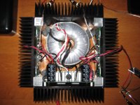
On that same note, I have attached a picture of my finished F5 (well almost finished, you know how it is)
I got the offset down to 0.01mV, rails are at 23.95 but they move around a little bit during the day depending on the wall voltage. Heatsinks are 51C directly behind the fet, and about 47C elsewhere with a 24C ambient. THD+N was 0.002 for the first channel, and 0.009 for the second, but it trimmed down to 0.003 with a lot of patience. All measured with an AP2 at 1 watt 1kHz and with a lab supply.
The AP wouldn't measure past 200kHz, but using a scope it looks flat out to about 600kHz, where it starts to drop off.
Now, I have two small issues that I'm a little curious about. The first is THD+N performance with the unregulated supply. When I substitute the lab supply with the unregulated one, the THD+N numbers jump up to 0.009 and 0.0101. The distortion vs. Freq also shows a bump at 60Hz and a notch at 120Hz, indicating that the added noise it definitely from 60Hz hum and the rectifiers.
Any suggestions on how to reduce this noise? All the above measurements were taken with the transformer well away from the chassis (not mounted in the middle like you see in the picture) so I don't think it's induced noise.
The second problem I was having was with square waves. I was looking at the square wave response at 200kHz, and I noticed that they didn't look that great (overshoot mostly). When I put the input up on the scope as well, I notice it was distorted too, and was overshooting in a similar manner to the output. I swapped the generator for a much better unit, and I got the exact same distortion on the input. When I disconnected the generator from the F5 the square wave went back to normal. This seemed to start happening at about 60kHz and got worse and worse the higher I went. If anyone knows what is causing this, please let me know.
Cheers,
Owen
Hi Roumen,
The boards are here, I've built up and tested my set, and I only have two more single channels available to sell. All the other boards went pretty quickly. If there's enough interest I might have a proper run done which would further reduce the cost.
I'll set aside the last pair for you if you're interested. They're $15 each, and I have enough parts around here to put together a kit if you'd like.
Send me a PM and I'll email the PDF files and price list.
On that same note, I have attached a picture of my finished F5 (well almost finished, you know how it is)
I got the offset down to 0.01mV, rails are at 23.95 but they move around a little bit during the day depending on the wall voltage. Heatsinks are 51C directly behind the fet, and about 47C elsewhere with a 24C ambient. THD+N was 0.002 for the first channel, and 0.009 for the second, but it trimmed down to 0.003 with a lot of patience. All measured with an AP2 at 1 watt 1kHz and with a lab supply.
The AP wouldn't measure past 200kHz, but using a scope it looks flat out to about 600kHz, where it starts to drop off.
Now, I have two small issues that I'm a little curious about. The first is THD+N performance with the unregulated supply. When I substitute the lab supply with the unregulated one, the THD+N numbers jump up to 0.009 and 0.0101. The distortion vs. Freq also shows a bump at 60Hz and a notch at 120Hz, indicating that the added noise it definitely from 60Hz hum and the rectifiers.
Any suggestions on how to reduce this noise? All the above measurements were taken with the transformer well away from the chassis (not mounted in the middle like you see in the picture) so I don't think it's induced noise.
The second problem I was having was with square waves. I was looking at the square wave response at 200kHz, and I noticed that they didn't look that great (overshoot mostly). When I put the input up on the scope as well, I notice it was distorted too, and was overshooting in a similar manner to the output. I swapped the generator for a much better unit, and I got the exact same distortion on the input. When I disconnected the generator from the F5 the square wave went back to normal. This seemed to start happening at about 60kHz and got worse and worse the higher I went. If anyone knows what is causing this, please let me know.
Cheers,
Owen
Attachments
Roumen,
I forgot to mention that I'm actually in Ottawa now (I just updated my profile). I went to school in Toronto but I neglected to change my location when I moved here 6 months ago.
As far as heatsinks go, I used to buy mine from R-theta who are located in Toronto. If you're gutsy you can also grab a flashlight and go dumpster diving there at night, but I suppose it would be more dignified to just go and ask them if they have some end cuts they would sell you for cheap. I bought mine cut and anodized, and they were a little expensive, but very nice heatsinks.
Also, check out Active Surplus on Queen street (with the giant gorilla) They often have some excellent amplifier parts in there (heatsinks, toroidal transformers, caps, etc...). Every time I go back to Toronto, I check that store out and stock up on goodies.
Cheers,
Owen
Attachments
Owen,
I think (even though I might be wrong) that you missed one maybe crucial detail, the input fets are placed far from each other and it would be wise to thermically couple them to each other. I couldn't get a figure on DC offset when I was setting up my F5 clone, that is, I constantly had (and still do get) 0.000 DC figure (@200mV range) and didn't measure it on any special or advanced equipment. No hum or noise. But, the input fets (170/74) are matched to identical characteristics and coupled together. The PS is somewhat beefier as well, 2x22mF+R22/25W-per rail+4x33mF per channel.
I think (even though I might be wrong) that you missed one maybe crucial detail, the input fets are placed far from each other and it would be wise to thermically couple them to each other. I couldn't get a figure on DC offset when I was setting up my F5 clone, that is, I constantly had (and still do get) 0.000 DC figure (@200mV range) and didn't measure it on any special or advanced equipment. No hum or noise. But, the input fets (170/74) are matched to identical characteristics and coupled together. The PS is somewhat beefier as well, 2x22mF+R22/25W-per rail+4x33mF per channel.
Input JFETs
Hi stein2
I debated the input jfet thing for a while (see my earlier post) and I settled on the current arrangement which favored layout over the close coupling of the jfets.
I messed around a little bit with this once they were built, and I found that if I physically grabbed one of the two jfets then I could make the output DC drift from less than 0.01mV to closer to 10mV, but under normal operation, the output doesn't wander around. I can also deflect it by about 3 mV if I blow really hard on jfet section. In either case the output slowly settles back to below 1mV. Neither of these things will even happen under normal operating conditions, and I expect the output to be even more stable when I put a top and bottom on, effectively making it a little heat box in there.
If this is a real concern for some people, then you can always leave the jfet legs longer, bend them 90 degrees, and couple the tops of the two devices in the middle of the board with some heatsink compound. When I revise the board I might move the jfets closer to one another to make this easier. coupling them face to face means flipping one around, which means running a feedback trace directly over the input trace, which spells trouble for me with such a high bandwidth design.
Having the thermistors mounted directly on top of the fets also really helps with stability. This thing biases up very quickly, and needed very little adjustment after initial setup.
Cheers,
Owen
Saturday afternoon listening
Done and done!
I've got it on as we speak! The new Mogwai album "The Hawk is Howling" sounds excellent on the 180g vinyl release.
I really like this amplifier, but I've only got a few days of listening under my belt so I won't splurge on the details. It does sound good though, very very good.
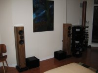
I've attached a picture of my setup with the new F5 sitting on the floor off to the side. You can see my Aleph 2's beside Lynn Olsen's Ariels, and to the right is my equipment rack which houses the turntable, a BZLS preamp, the Aleph Ono phono preamps, and a Resolution Audio CD50 CD player. Behind that is my sonotube subwoofer with a 6.5" TB driver in a 40Hz tuned line. Kinda like a miniature El-pipo.
Needless to say I'm a big fan of Pass Labs stuff...
Three cheers to Nelson for another incredible design!
Owen
Done and done!
I've got it on as we speak! The new Mogwai album "The Hawk is Howling" sounds excellent on the 180g vinyl release.
I really like this amplifier, but I've only got a few days of listening under my belt so I won't splurge on the details. It does sound good though, very very good.
I've attached a picture of my setup with the new F5 sitting on the floor off to the side. You can see my Aleph 2's beside Lynn Olsen's Ariels, and to the right is my equipment rack which houses the turntable, a BZLS preamp, the Aleph Ono phono preamps, and a Resolution Audio CD50 CD player. Behind that is my sonotube subwoofer with a 6.5" TB driver in a 40Hz tuned line. Kinda like a miniature El-pipo.
Needless to say I'm a big fan of Pass Labs stuff...
Three cheers to Nelson for another incredible design!
Owen
Attachments
Re: Saturday afternoon listening
I matched my F5 with a modded NS10 and ZenMod's "Shiny" PS and ESLs which were turning on the protection on NAD2600 (2x150W/8), and no problems with F5... and only 25 watts... Gooood 25 ones, tho!
opc said:Done and done!
I've got it on as we speak!
<snip>
Three cheers to Nelson for another incredible design!
Owen
I matched my F5 with a modded NS10 and ZenMod's "Shiny" PS and ESLs which were turning on the protection on NAD2600 (2x150W/8), and no problems with F5... and only 25 watts... Gooood 25 ones, tho!
Hi Owen,
Thanks for your reply. I am definetly interested in the pcb's and any part needed to complete the F5.
I am still under moderation (haven't posted anything), and don't have access to your e-mail.
You can e-mail me with the list of components and price.
Thanks again,
Roumen
Thanks for your reply. I am definetly interested in the pcb's and any part needed to complete the F5.
I am still under moderation (haven't posted anything), and don't have access to your e-mail.
You can e-mail me with the list of components and price.
Thanks again,
Roumen
rsotirov said:Hi Owen,
Thanks for your reply. I am definetly interested in the pcb's and any part needed to complete the F5.
I am still under moderation (haven't posted anything), and don't have access to your e-mail.
You can e-mail me with the list of components and price.
Thanks again,
Roumen
Owen,
Just realized that being under moderation, you don't have access to my e-mail.
So, here it is: rsotirov@hotmail.com
Thanks,
Roumen
- Home
- Amplifiers
- Pass Labs
- F5 power amplifier