Hi Guys,
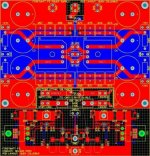
I've attached a final screen-shot of the PCB I'm sending off to be made on Monday. I've only included the PS and one channel, but I managed to fit two more channels below that.
I got rid of the B1 circuit, and used the space for an extra F5 channel, so I'll have five power supplies, and 15 channels total. I'm keeping one PS and two channels for myself.
Now, I have a bone to pick about the whole "JFETS must be touching thing". I've read over the whole thread, and some people have done this, while others haven't (namely Nelson himself, Jackinnj, etc).
If the point is to keep the JFETS at the same temp to prevent thermal drift, then I suggest the following:
1. If they're both mounted on the same board, in the same chassis within 1" or so of each other, they're pretty likely to be very very close in temperature anyhow.
2. If the dissipation of the device itself is causing the temp drifting, then putting the cases face to face probably leaves a good 100 degrees C/watt difference from one die to the other, so I doubt it's doing much.
Can someone comment on the legitimacy of this practice? If people are making a mess of the most critical portion of the layout just to get two JFETS to touch for no reason, then it would be nice to make it clear. All the amps built without contact seem to be working just fine. Thermal stability seems to be dominated by the proper use of the thermistors, and not by the JFETS.
I've tried to optimize the following on my boards:
1. High power traces are as large as possible
2. Input is kept a good distance from output
3. Thermistors are very well coupled to the FETS
4. Fets are nice and far apart (about 5")
5. Feedback path is short and runs directly from output to JFETS.
6. Distance from gate stopper to gate is very short
7. Star grounding used on the F5 channel itself
8. Shaped ground plane used on PS
9. SMD parts minimize lead inductance/signal length
10. All thermistors, fuses etc... included on PS - just add a transformer!
I'm still open to any comments on the layout, so please let me know if you spot anything. The boards are going into an old school pass labs style chassis with heatsinks on all four sides. One channel will be on the left, one channel on the right, the PS board on the front heatsink, and connectors will be on the back heatsink. XFMR will wit in the middle, and will be well shielded with copper.
Cheers,
Owen
(Again, sorry for the terrible screenshot. 104kB is not an easy target to meet. If anyone wants a proper PDF with the schematics and layouts, just email me and I'll send it to you)
Attachments
EUVL said:It was published in the thread around P.48, just go thru it pls.
Patrick
EVUL,
just two curiosity:
- i have opened the PDF file was attached back then i I have noticed you made a spectrum analysis up to 2MHz.
Was that the result of a simulation or what kind of program/Hardware did you use?
- where did you get the small (90.22ohm 0.18ohm) PRP 5W? and how much did you pay for them?
thanks for your attention.
> Was that the result of a simulation or what kind of program/Hardware did you use?
Measured data using a Handyscope 3.
> where did you get the small (90.22ohm 0.18ohm) PRP 5W? and how much did you pay for them?
Using 0.18R 5W was actually MPC74 from Fu-Futaba.
http://www.fu-futaba.co.jp/
Otherwise multiple 0.25W and 1W PRPs in parallel to make up the value and power.
Patrick
Measured data using a Handyscope 3.
> where did you get the small (90.22ohm 0.18ohm) PRP 5W? and how much did you pay for them?
Using 0.18R 5W was actually MPC74 from Fu-Futaba.
http://www.fu-futaba.co.jp/
Otherwise multiple 0.25W and 1W PRPs in parallel to make up the value and power.
Patrick
Hello (sorry for my poor english)
I will soon build a F5 and I have some questions.
Why not putting Q1 and Q2 close to create a thermal link between these 2 fet ?
Do you think possible to do F5 without PCB (I mean printed circuit board) like vacuum amp, so no probleme of skin effect and better sound ? I hesitate because I fear some oscillations.
Thank you M. PASS for your work. For me you're a legend.
David
Modifying F5 for high voltage
Hi everyone,
I want to amplify the signal (not audio) using Nelson Pass F5 amplifier to a high capacitive load (nanoFarads). The Frequency response 100kHz is also perfect for my application.
But I need to amplify a HIGH VOLTAGE triangle-rising-voltage pulses of up to 300 Volts peak value.
Could someone please advise me is it possible to redesign the F5 circuit for this high voltage? I realize it would need new transistors, but since I am not in the field, I do not know if there are such transistors with suitable specifications.
Sincerely,
Al.
marieda63 said:Why not putting Q1 and Q2 close to create a thermal link between these 2 fet ?
Do you think possible to do F5 without PCB (I mean printed circuit board) like vacuum amp, so no probleme of skin effect and better sound ? I hesitate because I fear some oscillations.
Thank you M. PASS for your work. For me you're a legend.
David [/B]
My F5 was built on PCB designed by Borko_KA and the Q1/Q2 are thermally coupled via some thermal paste and tightened together with a zip-tie.
Do not fear from oscllations, this amplifier is the quietest amp I have ever heard! With 95dB sensitive Fostex horns and ear almost on the membrane, nothing, not even during switching on or off. It took me a lot of time to get my guts together to start and turn it on for the first time, but from that moment on, it all went much better than I could ever imagine. So, dig into the thread, see the PCB design and rest assured that with that layout, there shouldn't be a single problem, as long as you follow the schematic. Good Luck!

Re: Modifying F5 for high voltage
Why not use tubes then? To play with 300Vpp signal, the power supply would have to be over that voltage. But, maybe someone would use a bulldozer to move a feather...

high5 said:Hi everyone,
I want to amplify the signal (not audio) using Nelson Pass F5 amplifier to a high capacitive load (nanoFarads). The Frequency response 100kHz is also perfect for my application.
But I need to amplify a HIGH VOLTAGE triangle-rising-voltage pulses of up to 300 Volts peak value.
Could someone please advise me is it possible to redesign the F5 circuit for this high voltage? I realize it would need new transistors, but since I am not in the field, I do not know if there are such transistors with suitable specifications.
Sincerely,
Al.
Why not use tubes then? To play with 300Vpp signal, the power supply would have to be over that voltage. But, maybe someone would use a bulldozer to move a feather...
But I need to amplify a HIGH VOLTAGE triangle-rising-voltage pulses of up to 300 Volts peak value.
I can't see a way to achieve this with this amp. As I see it you need something completely different.
Have fun, Hannes
Re: Re: Modifying F5 for high voltage
Thanks for reply
What do You mean by tubes?
stein2 said:
Why not use tubes then? To play with 300Vpp signal, the power supply would have to be over that voltage. But, maybe someone would use a bulldozer to move a feather...
Thanks for reply
What do You mean by tubes?
Re: Re: Re: Modifying F5 for high voltage
I mean Roehren, Valves... Not necessarily radio tubes, but to get the device swing at 300Vpp you must raise the supply voltage of the output MosFets at least a couple of volts over that figure, at least by some 4V (meaning at least +/- 155VDC and the modification of F5 would have to be so extensive that by all means it would be much better to use an already existing and proven circuit to use it for whatever you need it for. I mean this is like asking if you can modify a spoon to paddle a galleon... Sure, possible but it's really like
high5 said:
Thanks for reply
What do You mean by tubes?
I mean Roehren, Valves... Not necessarily radio tubes, but to get the device swing at 300Vpp you must raise the supply voltage of the output MosFets at least a couple of volts over that figure, at least by some 4V (meaning at least +/- 155VDC and the modification of F5 would have to be so extensive that by all means it would be much better to use an already existing and proven circuit to use it for whatever you need it for. I mean this is like asking if you can modify a spoon to paddle a galleon... Sure, possible but it's really like
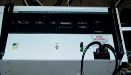
You need one of these, not an F5 -- a Fluke 5205 used with their A.C. calibrator -- will drive anything -- the new Fluke A.C. amplifier costs around ten kilo-bucks.
and at any rate, I would hardly call the F5 a linear amplifier for instrumentation purposes over a few tens of kHz --
and at any rate, I would hardly call the F5 a linear amplifier for instrumentation purposes over a few tens of kHz --
Attachments
marieda63 said:Thanks for reply, Stein2
For the power supply, I will use the regulated PS of zenV5. It should allow me to use less electrolytic capacitor.
I find vishay 1/2W et Philips 2W resistors metal film 1% for PS and amp
A+
David
You don't really need regulated supply, and at 24VDC, it shouldn't be hard or too expensive to get 40V capacitors. Even for me in Serbia it wasn't a problem to collect 264.000uF for my F5. And I bet you make at least that much money as I do
stein2 said:You will most likely have to change a couple of values of elements to be able to set it up properly. With +/-25, no additional fiddling is required, so my guess is that even with the extra 6 volts it wouldn't be a huge problem, but the dissipation will most likely increase... I really have huge heatsinks and it maybe is the way to go, (that definitely is) and maybe you'll find out if you try it.
thanks stein & Zen Mod for answering my newbie questions.Zen Mod said:in case of 2sj74/2sk170 as input devices , +/-28V is pretty close to their voltage limits ...... at least during setting procedure , where they could likely see full rails .........
with that rails - you can use mosfet cap multipliers , with benefit ........
that way , you'll loose exactly what's needed - ~ 4V on each rail , with miniscule dissipation increase
my worry is, I'll be using un-regulated power supply, means the rail voltage is depends on the transformer ratio.
I measured my house supplies, and sometimes, it'll fluctuate from 220V to 250V.
If I set 230V as my target input, with ratio 1:9, I'll get my target 25V at rail.
However, when the input voltage fluctuates to 250V, my rail voltage will go to around 27V - 28V.
what can I do in order for me no to fry my F5?
Don't plan to put a voltage regulator though.
calvinhpk said:
thanks stein & Zen Mod for answering my newbie questions.
my worry is, I'll be using un-regulated power supply, means the rail voltage is depends on the transformer ratio.
I measured my house supplies, and sometimes, it'll fluctuate from 220V to 250V.
If I set 230V as my target input, with ratio 1:9, I'll get my target 25V at rail.
However, when the input voltage fluctuates to 250V, my rail voltage will go to around 27V - 28V.
what can I do in order for me no to fry my F5?
Don't plan to put a voltage regulator though.
is that toroid xformer ?
if yes - you can easily unwound several turns , and have 2x18-19Vac
Zen is right, even I managed to easily pick out the middle points from a 500VA 2x35VAC transformer and make a 18-0-18 + 18-0-18 VAC transformer... It was originally wound for a Quad405 replica. Now it's a dual mono supply with a common core
To comfort you, in some extreme cases, the mains fall to 170V in the house, and in some other cases, whirl up to 250V for moments, and unlike my UPS for PC, the F5 doesn't seem to complain ... In normal circumstances, the rail voltage stands still at 23.4VDC... Theoretically, the DC voltage would raise to 26.59VDC at times when the mains voltage gets to 250... No problems... so far...
Maybe this is too far fetched, but maybe if you slightly increase the value of the PSU resistor in series (I used 0.22Ohm/25W) and slightly reduce the parallel resistor value from 2k2 it could affect the final DC voltage, but the simplest and safest would be to play with a few winds off and sleep peacefully...
calvinhpk said:
what can I do in order for me no to fry my F5?
Make sure you have plenty of fuses. Put a fast blow in each of the positive and negative supply lines.
The thermistor + ZTX450/550 version of the F5 is easier to adjust and has somewhat lower THD% as well.
Renesas fets for Toshibas, etc
Just a quick 'off topic' query - please excuse if already answered -
Is it possible[ or advisable ] to use the Renesas/Hitachi 2SK1058/2SJ162 instead of the Toshiba 2SK1530/2SJ201 (Patrick post 1190) or the "standard" IRFP240/9240s, and FQA19N/12Ps?
Just a quick 'off topic' query - please excuse if already answered -
Is it possible[ or advisable ] to use the Renesas/Hitachi 2SK1058/2SJ162 instead of the Toshiba 2SK1530/2SJ201 (Patrick post 1190) or the "standard" IRFP240/9240s, and FQA19N/12Ps?
- Home
- Amplifiers
- Pass Labs
- F5 power amplifier