Nelson Pass said:Overall, the amplifier still has a positive tempco.
Then it must be from jfets. Not sure, but using V-grade may help.
Vgsth, that is the Gate to Source threshold voltage, goes down with temp (ussually a few mV/C). However, the "TempCo" we are normally concerned with would be the Id current change with temp. This is a possitive figure. 
Considering our normal operating area, holding Vgs and Vds constant the Id will rise with temperature. With Vgs constant and a negative threshold tempco, this is to be expected. However, looking at the typical transfer characteristic graph, this only holds true up to about 13A for the IRFP240. At which point you would say the "tempco" is 0. Id does not change with temp.
It woud sure be nice if we could operate close to 13A Iq in our amps but that is not very practical. It would however give thermal stability.
One of the benifits of the Lateral MOSFET devices is that their 0 tempco point is 1-2 amps. Hmmm. A big negative however is their gain S*(&ks
My F5
Hi,
First of all I have to thank Nelson for his design, and also thanks Juma for his PCB layout.
I've been reading the thread couple times and Nelson's F5 article on first watt before I start making this amp.
I've it set-up today and have it run for about 3 hours and both channel fire up at the first time. The bias is quite easy to adjust, but I still have the following questions.
1). After 3 hours, I have 0.595v across the o,47R resistor and it's bias is +2mv to -2mv range. Is it normal?
2). The temperature on heatsink is 38C, and my heatsink is 7" x 14" x 3". Will it run really hot if I turn on for more than 6 hours?
If not I'd love to change that 0.47R resistor to 0.33 and run them at 1.8A. Please advise.
Albert
Attachments
Re: My F5
Hi Albert,
1) It's not normal - it's great ! You got very stable bias
2) 38C is a great result, Mr. Pass usually aims for 50-55C. You have wide enough margin to try higher bias. Do it in steps, set bias to 1.5A for couple of hours and if everything is OK, go for 1.8A - the idea is to have temperature on heatsinks less or equal to 55C (the cooler, the better). You don't have to change 0.47R resistors in order to change the bias, do it with trimmer pots on PCB (0.705 V on 0.47R resistors will give you 1.5A bias, 0.846 V for 1.8A ).
Keep up the good work
albertli said:...
1). After 3 hours, I have 0.595v across the o,47R resistor and it's bias is +2mv to -2mv range. Is it normal?
2). The temperature on heatsink is 38C, and my heatsink is 7" x 14" x 3". Will it run really hot if I turn on for more than 6 hours?
If not I'd love to change that 0.47R resistor to 0.33 and run them at 1.8A. Please advise.
Albert
Hi Albert,
1) It's not normal - it's great ! You got very stable bias
2) 38C is a great result, Mr. Pass usually aims for 50-55C. You have wide enough margin to try higher bias. Do it in steps, set bias to 1.5A for couple of hours and if everything is OK, go for 1.8A - the idea is to have temperature on heatsinks less or equal to 55C (the cooler, the better). You don't have to change 0.47R resistors in order to change the bias, do it with trimmer pots on PCB (0.705 V on 0.47R resistors will give you 1.5A bias, 0.846 V for 1.8A ).
Keep up the good work
Albert, be careful with increasing the bias.
You'll approach 45W dissipation per device, this is a lot.
There is a Junction to case and case to sink thermal resistance.
The junction temperature of the MOSFET's will be considerably higher with 45 Watts and 55°C sink temperature than with 30W and say the same 55°C sink.
Tino
You'll approach 45W dissipation per device, this is a lot.
There is a Junction to case and case to sink thermal resistance.
The junction temperature of the MOSFET's will be considerably higher with 45 Watts and 55°C sink temperature than with 30W and say the same 55°C sink.
Tino
Thanks guys,
I didn't have chance to put any music on yet.
I certainly will let it sing for a week or two, then I'll follow Juma's idea to adjust the bias bit by bit carefully.
Thanks again. Will post result
Albert
BTW both 0.47R sit around 40C, does it matter? how high it can go and without burning it?
I didn't have chance to put any music on yet.
I certainly will let it sing for a week or two, then I'll follow Juma's idea to adjust the bias bit by bit carefully.
Thanks again. Will post result
Albert
BTW both 0.47R sit around 40C, does it matter? how high it can go and without burning it?
595mV across 0r47 is just 0.75W.
What size (dissipation) of emitter resistor are you using?
Andrew, I'm using 3w resistor which is same as schematic.
My F5 is very stable on both channels. I turned it on before I gone to work this morning and I have almost 2 hours listening section after I came home - totally 11 hours. I took the measurement again after the listening section and everything remains the same. The temperature is still 38C.
Many guys talked about how good the sound is. I thought I'm not qualified to say anything about the sound, but I'm really happy with this amp. Only after the first 2 hours listening, I like this amp even more than my tube amps. It sounds really mellow and tubie and the sound stage is wide. Bass is deep and tight.
I'll let it run for another week and will try tune the bias to 1.5A. ( 0.705v across 0R47 )
Albert
albertli said:temperature on heatsink is 38C
You should call it the Fridge-Five.
Biased at 1.8A, the dies of IRFP output devices would still be under 100C, assuming 25C ambient and say 0.5C/W added thermal resistance for the insulator pad.
Fairchild FQA devices would be a more convenient choice for such a high dissipation number in that setup, nearly 10C more slack.
100C die temperature may not be the ticket for serial manufacturing, but should work flawless in most cases and DIY is pretty service friendly.
I've got Sanken power devices operating at 100C die temperature in an ExtremeA power amp, there's no way for me to drop it to a lower value, but none have pushed up daisies yet.
Statistically, there's not a longevity issue for a die temperature at 100C, just the rotten apple will pop up his head.
Juma,
I did try to up a bigger picture, but the site didn't allow me to do that. Is there any other way I could try, or I email you.
Jacco,
I've 56C on both IRFs now. Do you mean I won't kill the IRFs within 100C????? I'd love to run it hot.
Can you tell me the different how much better if I run it at 1.5A and 1.8A
Thanks
Albert
albertli said:Juma,
I did try to up a bigger picture, but the site didn't allow me to do that. Is there any other way I could try, or I email you.
Jacco,
I've 56C on both IRFs now. Do you mean I won't kill the IRFs within 100C????? I'd love to run it hot.
Can you tell me the different how much better if I run it at 1.5A and 1.8A
Thanks
Albert
I sent you an e-mail about pictures.
With 56C on IRFs you are in the safe zone. Generally, class A amps tend to sound better with higher bias.
How much better is 1.5A/1.8A than 1.3A is up to you to decide after you try it
Vertical MOSFETs are used for a load of other stuff besides audio, operational lifetime cycle of these devices is pretty steep, think 50 years.
At less elevated die temperatures you'd be dead and burried before they (all) pop, 100C is acceptable if it's not the last DIY power amp you'll ever build.
A number of wellknown serial production amps were designed for really steep die and heatsink temperatures.
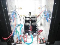
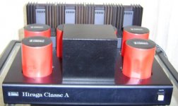
Best example is the 30 Watter Hiraga with BJT output devices, more than a few needed repair but a lot of them managed +20 years.
The 60W power devices of the Hiraga each ran at a 30W dissipation level, with small heatsinks good for 125C die temperature.
High die temperatures of BJT power devices usually destroy them because of the combination of reduced safe operating area and second breakdown effect.
BJT power amps such as the Hiraga and ExtremeA manage to survive due to the very moderate rail voltage levels.
Vertical MOSFETs do not suffer from second breakdown, just thermal runaway due to a positive tempco.
Do a search, some of the paesanos here have run vertical MOSFETs at very high die temperatures for long periods without any hassle.
(d., i'm a walking talking phone book)
Ask Papalala about bias level of V's and SQ.
At less elevated die temperatures you'd be dead and burried before they (all) pop, 100C is acceptable if it's not the last DIY power amp you'll ever build.
A number of wellknown serial production amps were designed for really steep die and heatsink temperatures.
Best example is the 30 Watter Hiraga with BJT output devices, more than a few needed repair but a lot of them managed +20 years.
The 60W power devices of the Hiraga each ran at a 30W dissipation level, with small heatsinks good for 125C die temperature.
High die temperatures of BJT power devices usually destroy them because of the combination of reduced safe operating area and second breakdown effect.
BJT power amps such as the Hiraga and ExtremeA manage to survive due to the very moderate rail voltage levels.
Vertical MOSFETs do not suffer from second breakdown, just thermal runaway due to a positive tempco.
Do a search, some of the paesanos here have run vertical MOSFETs at very high die temperatures for long periods without any hassle.
(d., i'm a walking talking phone book)
Ask Papalala about bias level of V's and SQ.
Attachments
albertli said:
Jacco,
I've 56C on both IRFs now. Do you mean I won't kill the IRFs within 100C????? I'd love to run it hot.
Can you tell me the different how much better if I run it at 1.5A and 1.8A
Thanks
Albert
Hmm, I'm positively sure I'm not Jacco (at least I like to think that the guy in the mirror is somewhat younger)

Anyhow, you can run an IRFP240 at 3A 40V for a looooong time, without problems. Just keep in mind that you need some respectable thermal mass to keep them from going over the edge, and naturally some pretty massive heatsinks.
Been there, done that.. (actually am still there), and love the sound of it.
I don't think you can tell 1.5A from 1.8A, but 2.5A or 3A will sure make a (to me) positive difference.
Magura
- Home
- Amplifiers
- Pass Labs
- F5 power amplifier