khaho said:the layout of boards in F4 manual.
Pretty neat too with the steering wheel pads.
The F5 performance is really impressive. Very simple circuit and easy to build. I like the mid to high response of the amplifier, it's warm and gives more detail compare to my other amplifiers. As what DUC985 mentioned, absolutely dead quite even you put your ears close the speaker like a headphone, you will not hear any hum and turn on thumb.
Many, many thanks to Nelson for sharing this design to DIY community.
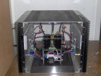
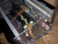
Here's a picture of my DIY F5 on Plexiglass. I don't have the budget to buy an aluminum for front and back panel yet, so I decided to use a plexiglass for the meantime. The transformer is Piltron 300VA 18 - 0V dual. To get the maximum performance, I'm planning to replace it with 400VA 20 - 0V dual as what Jack used on his amp. The capacitors used were 33,000 uF each, which is 66,000 uF in total per rail. I bought the heatsink from Steve at Apex Jr.
Just build it and hear it. You won't regret it.
Many, many thanks to Nelson for sharing this design to DIY community.
Here's a picture of my DIY F5 on Plexiglass. I don't have the budget to buy an aluminum for front and back panel yet, so I decided to use a plexiglass for the meantime. The transformer is Piltron 300VA 18 - 0V dual. To get the maximum performance, I'm planning to replace it with 400VA 20 - 0V dual as what Jack used on his amp. The capacitors used were 33,000 uF each, which is 66,000 uF in total per rail. I bought the heatsink from Steve at Apex Jr.
Just build it and hear it. You won't regret it.
Attachments
fredlock said:Another view...
very cool. Black cube. Looks like my F2. I mounted the power supply from the top.
I tried using a sheet of plexi for a cross-over earlier this year, must of ordered the wrong grade or something, as whenever I drilled it, it cracked bad. I had some older stuff I used a few years back that had no such trouble.
Mike
udailey said:I have some acrylic. It drills pretty nicely. Love using that stuff for placing RCAs that dont have plastic insulating washers.
Uriah
Uriah,
Do you know what grade of acrylic to order?

I was thinking an see-through top to show some blue LED glow.
Mit,
Thanks for asking. I went to get the leftovers to see what the sticker on them said in regards to your question.
Its actually Lexan. Its XL10 and I dont know if this makes any difference, but it is UL972-Burglary resistant. Maybe whatever they do to make it burglary resistant also makes it not chip or crack when I drill into it. Since I just use it for the back panel its only about 3/16" thick.
I only use it for the back of my amp where the RCA connectors go. I drill a hole in the wood that is bigger than the back of the connector. Then I drill into the lexan. Screw the RCA together on the Lexan and then push RCA connectors into the holes in the wood and screw the Lexan into the wood. Its not much extra work at all and you can put whatever color paper/plastic you want on the back of the Lexan to have a nicer looking panel. I dont do any leds so I wouldnt know the Lexans performance with this or how to polish the edges to get that nice glow. I cut the lexan with regular drill bits and a small tooth hand saw.
I got the Lexan at Lowes.
Uriah

So what about the bass? Middle of the road, lacking, non-existent? Or do you think its the smaller supply?
The bass is pretty good! I can't complain about it but I think you can make it better with the higher transformer rating IMHO.
Hi Fredlock, some questions about your "transparent" amp:
- could you give me the rough dimensions of the heatsinks?
- are you biasing it as per the F5 article, i.e. 1.3A/MOSFET?
- how hot are your heat sinks getting?
I have similar sinks and thought they are insufficient, but maybe....
Thanks anyway
Tino
amp:- could you give me the rough dimensions of the heatsinks?
- are you biasing it as per the F5 article, i.e. 1.3A/MOSFET?
- how hot are your heat sinks getting?
I have similar sinks and thought they are insufficient, but maybe....
Thanks anyway
Tino
Just a little note about Lexan. You can bend it like you would sheetmetal and it will not crack. Makes really nice rounded corners.When you drill and tap lexan you can see the threads, they look kind of cool. Has fabulous other desirable characteristics. Just do not get it near acetone. Tad
To Mr. Pass
Since you have gone to mostly TO-247 frame mosfets with most of your current designs, this one included, have you noticed any reliability issues as compared to the older TO-3 cases.
Being in the retail sector and using quite a few of these types of transistor should make you able to provide a quite accurate assumption.
Also, can you provide a rough percentage of beta test matches when purchased from a like lot number. I was quite happy with the results of my matching on my current project most of the units in a single tube fell into spec. Thanks Tad
Re: f5
They work fine. I have not encountered any issues, however I don't send
product into corrosive environments, etc, nor do I operate the devices near
their maximum ratings.
A couple of possibilities - your generator might be putting out DC or might
be sending the amplifier into oscillation. The latter will occasionally occur if
the output of the amp becomes coupled to the input through a shared
ground or through capacitance between input and output cables.
There is a practical reason why we don't extend the bandwidth of amplifiers
beyond 100 KHz in PL products - too many issues in the field.
tryonziess said:Since you have gone to mostly TO-247 frame mosfets with most of your current designs, this one included, have you noticed any reliability issues as compared to the older TO-3 cases.
They work fine. I have not encountered any issues, however I don't send
product into corrosive environments, etc, nor do I operate the devices near
their maximum ratings.
AMPMAN said:I have overshoot on the leading edge of the sqare wave of my f5 amp, also I cannot balance the voltage across the .47 resistors. the output voltage is ok but on one channel when I connect my signal generator the output goes to over 3 volts anybody?
A couple of possibilities - your generator might be putting out DC or might
be sending the amplifier into oscillation. The latter will occasionally occur if
the output of the amp becomes coupled to the input through a shared
ground or through capacitance between input and output cables.
There is a practical reason why we don't extend the bandwidth of amplifiers
beyond 100 KHz in PL products - too many issues in the field.
- could you give me the rough dimensions of the heatsinks?
Tino,
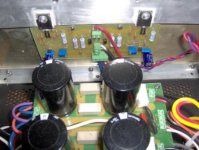
There are 2 heatsinks per channel joined togehter. The dimension is approximately 9 1/2 " x 12 1/2" plus the add on 1/4" thickness aluminum bar mounted on the heatsink with the MOSFETS.
- are you biasing it as per the F5 article, i.e. 1.3A/MOSFET?
Yes.
- how hot are your heat sinks getting?
I did not measure the actual temperature but my assumption would be 35 to 40 degrees.
fredlock said:my assumption would be 35 to 40 degrees.
Checks out with the geometry and sizes you mention.
Your heatsinks look similar to the popular 30-rib 1.6" thick SK56 overhere.
A 5'' length of SK56 does 0.40C/W, makes 0.20 C/W for 10 inches, 25% added for rotating them 90 degrees gives 0.25C/W.
Corresponds to 35C-40C at an ambient temp of 20 to 25C.
Spacy, you could make a 100W F5 monaural block with that case.
- Home
- Amplifiers
- Pass Labs
- F5 power amplifier