My primary objective right now is to make my amp work after experiencing a couple of setbacks, my main change this time around is that speaker return isnt going to the amp boards anymore but directly to the common point. And both rails are now directly connected to eachother, not shared via the longer 0V lines coming from both amp boards.
Last nite I went through the steps validating the integrity of the wiring, voltages were good, bulb went out and initial biasing went without issues - so as far as I am conserned the advice given and the path taken, appear to be sound. Building this amp is ment to be a learning experience, the next one will hopefully become even better. Any advice or thoughts given to me during this process have been appreciated.
Hi You ! Please read AN-202 !!!!!!!!!!!!!!!!!!!! Then consider each board a IC
Success?
The suspense is killing me!
I have gradually increased bias since yesterday morning and am currently at 0,6V on both boards. The amp is closed shut, top lid rest snuggly on top. Offset both sides 0,0V +\- 2mV
Amp #1 is the good one, amp #2 is the new one.
When top lid is removed #2 bias drop 30mV and #1 barely at all.
Heat sinks on #1 appear to be marginally degrees warmer to the touch than #2.
With lid back on #2 rise back to set bias value.
I am able to firmly put two fingers on all mosfets for ~2s without feeling pain.
Will check tension to heat sinks, #2 might not be equally tight as #1. Keratherm used. Temp.meter on heat sinks indicate 36-38degC which is only about 16deg above ambient.
Trim pots on both sides are a little finicy to adjust as initial movement may not give change before "suddenly" values change, like the change isnt linear to adjustment. Due to this I always increase a little too far and dial down to intended value.
Will keep an eye on the amp through day day and eventually cycle it cold/warm a couple of times. If all is good I will hook it up to a test speaker #fingerscrossed
I have done one restart from cold, initial value on #2 0,460 quickly rising up to 0,620 before settling in at 0,598V. Max offset 10mV going down as it heated up.
#1 had a less sharp bias peak and is more stable around its bias point.
Not sure why but the thermistors are touching the mosfets differently, could that be the cause for this?
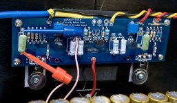
On #2 the thermistors full side touch silica while on #1 the thermistor edge touch at an angle. Image show #1.
I also have different 0,47R resistors, 5W on #1 and 3W on #2.
#1 had a less sharp bias peak and is more stable around its bias point.
Not sure why but the thermistors are touching the mosfets differently, could that be the cause for this?
On #2 the thermistors full side touch silica while on #1 the thermistor edge touch at an angle. Image show #1.
I also have different 0,47R resistors, 5W on #1 and 3W on #2.
Attachments
I have gradually increased bias since yesterday morning and am currently at 0,6V on both boards. The amp is closed shut, top lid rest snuggly on top. Offset both sides 0,0V +\- 2mV
Amp #1 is the good one, amp #2 is the new one.
When top lid is removed #2 bias drop 30mV and #1 barely at all.
Heat sinks on #1 appear to be marginally degrees warmer to the touch than #2.
With lid back on #2 rise back to set bias value.
I am able to firmly put two fingers on all mosfets for ~2s without feeling pain.
Will check tension to heat sinks, #2 might not be equally tight as #1. Keratherm used. Temp.meter on heat sinks indicate 36-38degC which is only about 16deg above ambient.
Trim pots on both sides are a little finicy to adjust as initial movement may not give change before "suddenly" values change, like the change isnt linear to adjustment. Due to this I always increase a little too far and dial down to intended value.
Will keep an eye on the amp through day day and eventually cycle it cold/warm a couple of times. If all is good I will hook it up to a test speaker #fingerscrossed
Very good that both channels are holding, with lid on. When I remove lid, my bias varies a little, but not by 30mV. You mean it drops from .60 to .30?
Seems like a bit much, but if it returns to .60....Maybe this will subside with breakin? Maybe its what Andrew was talking about with variation with thermistors? I just stuck mine over the Mosfets, slightly contacting them and nothing more.
As to the pots being a little "finicky" I can see that, I usually adjust in many small turns, some having no effect, then a little change. I try to prevent overshoot, but not always possible. When it goes smoothly, one side increases slightly, offset goes up a little. Turn other knob, offset zeros. Back and forth until as close to 0 offset and .59 or so bias.
I would have hooked a test speaker to it by now, but given the problems with the one channel I do not blame you one bit. When channel was rebuilt, that included new board right? Or just parts?
Rereading I see you replaced PCB. As to adjusting one channel and having it affect the other slightly, I suppose this is normal given the single power transformer...I used seperate power transformers, one for each channel, since they have their own power cord I did one at a time. It seems that at times, once I have both plugged in after adjusting, there needs to be a little more. Whether that is from the increased draw or just normal variance I cant say. Usually the effects of the lid going on and off dwarf it in any event.
Russellc
Last edited:
@ sangram:
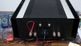
Picture doesnt tell but inputs are shorted (cable not connected to RCA and kept inside the cabinet.")
@Russel:
No, it drop from 0,600 to 0,570 before gradually climb towards 0,6 as it heats up. Its just an observation, not consern. I knew difference in thermistor placement would affect the circuit, but not to what extent etc - and I am curious.
The new board have fresh components except for Q1-Q6 which was pulled from the old board, they tested okay so I continued using them. The voltage fluctuations seen with the old board appear to be gone = Q1-Q6 wasnt the cause.
Yeah, when using two boards and one PSU voltage will sag when load is increased on one side thus affecting the other side.
Main voltage also change during the day so variations from that alone will give varying numbers, hopefully i have achieved a stable configuration
Picture doesnt tell but inputs are shorted (cable not connected to RCA and kept inside the cabinet.
@Russel:
No, it drop from 0,600 to 0,570 before gradually climb towards 0,6 as it heats up. Its just an observation, not consern. I knew difference in thermistor placement would affect the circuit, but not to what extent etc - and I am curious
. The new board have fresh components except for Q1-Q6 which was pulled from the old board, they tested okay so I continued using them. The voltage fluctuations seen with the old board appear to be gone = Q1-Q6 wasnt the cause.
Yeah, when using two boards and one PSU voltage will sag when load is increased on one side thus affecting the other side.
Main voltage also change during the day so variations from that alone will give varying numbers, hopefully i have achieved a stable configuration
@ sangram:
Picture doesnt tell but inputs are shorted (cable not connected to RCA and kept inside the cabinet.
@Russel:
No, it drop from 0,600 to 0,570 before gradually climb towards 0,6 as it heats up. Its just an observation, not consern. I knew difference in thermistor placement would affect the circuit, but not to what extent etc - and I am curious
The new board have fresh components except for Q1-Q6 which was pulled from the old board, they tested okay so I continued using them. The voltage fluctuations seen with the old board appear to be gone = Q1-Q6 wasnt the cause.
Yeah, when using two boards and one PSU voltage will sag when load is increased on one side thus affecting the other side.
Main voltage also change during the day so variations from that alone will give varying numbers, hopefully i have achieved a stable configuration
Oh, that tiny drop, in my totally uneducated opinion is nothing. Breathing may cause that, whipping the top off as well. Sounds like you have it in hand now! Must have been a intermittent board defect.
Russellc
@ sangram:
Picture doesnt tell but inputs are shorted (cable not connected to RCA and kept inside the cabinet.
Sounds good then! I couldn't see that in pictures.
30mV movement in bias is about 63mA over 0.47 ohms, or a bias drift error of 5% of 1.3A.
I wouldn't worry about it.
Oh, that tiny drop, in my totally uneducated opinion is nothing. Breathing may cause that, whipping the top off as well. .
By breathing on the new amp board I can make the bias voltage drop down to 0,500V, the other side barely move in comparison.
I have hooked the amp up to my receiver and connected speakers, its been playing solid for 2hrs now. It is slightly colder in the music room so bias seem stable in at 0,590V. Offset negligible
Volume appear to be down compared to my original amp but I haven't stressed the F5 yet. Speakers are DIY with a calculated efficiency of 100dB but I also tried it with B&W DM601S2´s. (Regular setup is Marantz SR5200 acting as pre with an Emotiva UPA5 power amp.)
It´s alive
Now I´ll let it settle in (recheck bias/drift) before starting to optimise the new system Sounds like its fine, the F-5 only has 15 dB of gain, the majority of amps have more. Build a BA-3 preamp next, it drives mine fine. You can also change the feedback resistors, but with 100dB speaks you should have plenty of gain, unless your pre doesnt have much gain. B-1 is insufficient for my uses with f-5, but my speakers are not that efficient.
I put my F-5 back in the system today for a few hours, at idle both channels .58 and .59, playing music upped them to .60, offset around 5 mV each channel. You will love the BA-3 pre, it will make up for lesser F-5 gain...again, with 100dB speaks you should have plenty.
Russellc
I put my F-5 back in the system today for a few hours, at idle both channels .58 and .59, playing music upped them to .60, offset around 5 mV each channel. You will love the BA-3 pre, it will make up for lesser F-5 gain...again, with 100dB speaks you should have plenty.
Russellc
The relative low gain was known so that is okay, I did manage to get a good hour in front of the speakers yesterday and dared pushing the volume up quite a bit - I can achieve pretty decent soundlevels
Bias of the one channel did drop a bit though (down to 0,450V, offset ~0) and remained there so I spent a litte more time tuning it. After spending the night cooking its now stable at 0,620V and 0,610V with sink temperature now at 41degC (At top of fins, vertically over the mosfets)
Fins now feel warm not just luke warm. Still a bit left before I would call it toasty as I can still rest my lower arms over the full lenght of the fins for a minute (as far as my patience allowed me)
(4U/40mm chassis)
I do hear a slight hum (perhaps not suprisingly ) from the speakers, one side being marginally stronger than the other. Swapping the speaker cables over made the other speaker the louder one. At listening position it is only detectable if everything else is quiet. Hum unaffected by position of volume knob.
Will investigate in a little while but for now I will keep monitoring bias/offset and nail that down, tune the F5 to my system and enjoy it a little bit
Bias of the one channel did drop a bit though (down to 0,450V, offset ~0) and remained there so I spent a litte more time tuning it. After spending the night cooking its now stable at 0,620V and 0,610V with sink temperature now at 41degC (At top of fins, vertically over the mosfets)
Fins now feel warm not just luke warm. Still a bit left before I would call it toasty as I can still rest my lower arms over the full lenght of the fins for a minute (as far as my patience allowed me)
(4U/40mm chassis)
I do hear a slight hum (perhaps not suprisingly
) from the speakers, one side being marginally stronger than the other. Swapping the speaker cables over made the other speaker the louder one. At listening position it is only detectable if everything else is quiet. Hum unaffected by position of volume knob. Will investigate in a little while but for now I will keep monitoring bias/offset and nail that down, tune the F5 to my system and enjoy it a little bit
Last edited:
I would not be scared to push it
F5 can run to a couple of volts from the supply rails and same what colder when doing so
Class A Yes?
Yes. I am currently at 615mV on both sides, offset 1mV and heat sink temperature is 40-41degC (about 105degF). Done a couple hot/cold starts and values are consistent.
Sink temperature is one thing and only worth its readings if the heat transfer between mosfet and heat sinks are good. I believe they are as I can touch the big washer with two fingers for a few seconds without getting burnt. I do not have a temp gun, wish I hade one, but temps of the 4 mosfets feel similar.
Regarding hum/noise:
I placed the F5 yesterday on my worktop with no signal input (input shorted) and hooked up one speaker to one channel.
Channel 1 = no audible hum/noise
Channle 2 = low audible hum/noise (this is the fresh board)
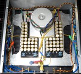
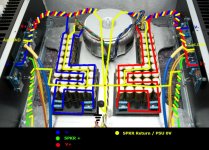
The only difference between the two boards (besides not being mirrored) is that their yellow GND do not go over the toroid but join on the right side of it before going to star ground. Hence channel 2 (left) have a slightly longer PCB return.
Attachments
Yes. I am currently at 615mV on both sides, offset 1mV and heat sink temperature is 40-41degC (about 105degF). Done a couple hot/cold starts and values are consistent.
Sink temperature is one thing and only worth its readings if the heat transfer between mosfet and heat sinks are good. I believe they are as I can touch the big washer with two fingers for a few seconds without getting burnt. I do not have a temp gun, wish I hade one, but temps of the 4 mosfets feel similar.
Regarding hum/noise:
I placed the F5 yesterday on my worktop with no signal input (input shorted) and hooked up one speaker to one channel.
Channel 1 = no audible hum/noise
Channle 2 = low audible hum/noise (this is the fresh board)
The only difference between the two boards (besides not being mirrored) is that their yellow GND do not go over the toroid but join on the right side of it before going to star ground. Hence channel 2 (left) have a slightly longer PCB return.
Sometimes a slight rotation of the transformer may affect this...also wiring location and so forth?
Russellc
Hello
I have just completed the assembly of a pair of F5 mono's, after success with biasing the first mono, I have cocked up the other with the most fundamental of mistakes!. I had the mosfets installed in the wrong positions, yes I know that is careless, maybe even stupid. Any idea what I have fried ?, apart from my pride.
Equipment = Cviller V 2.0 board, Fairchild FQA19N20C + FQA12P20 Mosfet.
1, Power supply tested with bulb tester and functioned satis before connection to board.
2, Power up to board was done with bulb tester in circuit, bulb did not go dim, power turned off .
3, No smoke or discernible smell.
4, Board disconnected form power supply, power supply functioned satis.
5, After a visual search the above was discovered.
Help needed please, I throw myself at your mercy!.
So U got Expensive fuses wlong way round but bulb did not go dim
Bulb did not go dim because it draw no currants (as in AMPs Like)
Put them back right way and try again after all U don't say U blow smoke and such so...
Just measure up those trimmers for starter
Next time try whit power supply wlong way round much funnier
Bulb did not go dim because it draw no currants (as in AMPs Like)
Put them back right way and try again after all U don't say U blow smoke and such so...
Just measure up those trimmers for starter
Next time try whit power supply wlong way round much funnier
Last edited:
- Home
- Amplifiers
- Pass Labs
- F5 power amplifier