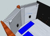
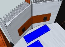
Do the heat sinks need to be thermally coupled to each other? Each output MOSFET will have 48 sq. in. of heat sink. The MOSFETS will be mounted off-board with short leads, so no need to bend the boards
The output offset is determined by the bias balance between the P and N channel devices, and the bias and temperature of the devices are quite intimately linked.
Good thermal coupling will keep the offset stable over time whereas separated sinks tend to show a bit of fluctuation as the bias moves up and down. This is not a temperature issue but is about the overall stability of the build.
Peter Daniel has posted a picture of some sinks which were separate but then he used some aluminum to couple the halves together. You can search the thread for his posts, there was some discussion of this issue during that time.
Thermally linking N sinks to P sinks is NOT equivalent to
intimately coupling N & P pairs.
The ideal power device layout would be an N & P pair in the same sink location and then all the parallel pairs spread across the sink.
Interleaving the Ns with the Ps gets close to that ideal.
Ns in a lower row and Ps in a high row is bad for Thermal Stability
Ns all at one side and Ps all at the other side is bad for Thermal Stability and worse than two rows.
Ns on a separate sink and Ps on a different sink is worst of all, especially if these are on different faces of a Chassis.
oloppolo - I suggest you change the input resistor (R5 in your schema) to something near 1K.
What's wrong with the 4.7k resistor in R5 position? I'm finishing my F5 in these days and I followed the schematic given in the F5 Turbo article where the input resistor is 4.75k, despite in a slight different position. I remember having read somewhere on this forum that one can use any of the two values (1k or 4.7k). If I'm doing something wrong I can still change back to 1k and I'd very much prefer doing it before soldering the mosfets...
Thanks for the help
Do you mean the measures to effect the thermal coupling between the sinks, or the need for thermally coupling them at all?
I'm just a greenhorn here with zero amp building experience (except what I've completed so far on the F5), so it's all theory to me. So if you're saying that a separate sink for each output device is not a problem, I'm happy to go with that. (I can always add bridges later if their lack causes issues).
I'm just a greenhorn here with zero amp building experience (except what I've completed so far on the F5), so it's all theory to me. So if you're saying that a separate sink for each output device is not a problem, I'm happy to go with that. (I can always add bridges later if their lack causes issues).
Given that they have the same size sink and are run at the same average
dissipation, they will tend toward the same temperature anyway.
The larger problem is that they temperature coefficients of the N and P are
not identical, and we depend on feedback to take care of that with regard to
DC offset.

dissipation, they will tend toward the same temperature anyway.
The larger problem is that they temperature coefficients of the N and P are
not identical, and we depend on feedback to take care of that with regard to
DC offset.
OK, so the bridges may not be necessary, but they can't hurt and may be beneficial. They would provide additional structural stability to the chassis, and aid in aligning the heat sinks. I guess the determining factor is whether or not we (my son & I) can fabricate them with the tools that we have...
Thanks Sangram and Andrew, and especially Nelson for your generosity in sharing your designs.
Wait till you see my ideas for the Amp Camp Amps
Thanks Sangram and Andrew, and especially Nelson for your generosity in sharing your designs.
Wait till you see my ideas for the Amp Camp Amps
I have a 11x6" copper bar of 8mm thickness connecting two sinks of a F5 Turbo build.
It is able to handle 20W of device dissipation (about 150mA on 4 devices on 35V rails) at 30 degree temperature rise. All by itself The good thing about copper is that it will soak heat very quickly and offer a larger surface area to the underlying sink than the devices mounted on it, which somewhat reduces the impact of two thermal junctions.
Your first idea looked a bit better overall, but I would listen to the master's advice on linking the heatsinks and whether it is at all required.
It is able to handle 20W of device dissipation (about 150mA on 4 devices on 35V rails) at 30 degree temperature rise. All by itself
Your first idea looked a bit better overall, but I would listen to the master's advice on linking the heatsinks and whether it is at all required.
I'll try the build w/out the bridge, based on Nelson's confidence in his design to compensate for the offsets  Assuming the amp works at all, if there's any instability detectable (and, at this point, I don't know how I'd analyze that), I can add the thermal bridge at a later time. This latest solution has the benefit of being easy to fabricate; just gotta put a 40 deg. bend in a small slab of copper (rather, two slabs).
When I was visiting my dad for Thanksgiving, I picked up his old NLS Miniscope. Don't know how to use it yet, but hopefully it'll be of some use in this endeavor.
Anyway, enough idle talk. Tomorrow we're cutting the heatsinks, hopefully without mangling them.
When I was visiting my dad for Thanksgiving, I picked up his old NLS Miniscope. Don't know how to use it yet, but hopefully it'll be of some use in this endeavor.
Anyway, enough idle talk. Tomorrow we're cutting the heatsinks, hopefully without mangling them.
I barely understand technical stuff myself (just enough to be dangerous), but I think that for a galvanic reaction to occur there needs so be an ionic path (e.g. an electrolytic liquid) between the two metals. I think this was discussed elsewhere in this (or another) thread.
@Hiten, yes this is true. Anodising and/or plating the surfaces is a way to prevent it. My sinks are anodised. Even in dry conditions the contact can and will corrode the aluminum. This is regardless of whether you have anything connected to them. The moisture in the air is usually enough to cause pitting in the aluminum.
However hybrid metal heatsinks are more common than you think, almost all CPU heatsinks are made this way, with a copper slug set in the aluminum base. There are enough ways around the issue.
However hybrid metal heatsinks are more common than you think, almost all CPU heatsinks are made this way, with a copper slug set in the aluminum base. There are enough ways around the issue.
I'm sorry but my F5 plays only with computers , smartphones , and mp3 player .oloppolo - I suggest you change the input resistor (R5 in your schema) to something near 1K. The 67K input shunt is fine. Everything else looks appropriate for a F5 with no limiter.
As Andrew says, with 220R feedback resistors your CD player should be able to drive the F5 to clipping.
No with B1 and other preamplifier between source and F5: decreases the level and the sound gets worse.

B1 is exellent with Gainclone.
Last edited:
Ah. I understand.
The reality of the 2V source is quickly and quietly going away with computer audio, and the necessity of a preamp with some gain is required for many users.
The F5 does act best when there is some gain feeding it. I have had very good luck with the BA-3 as preamp, the O2 headphone amplifier (fantastic), and similar circuits. You could use this as an opportunity to make a valve linestage or something interesting.
- Home
- Amplifiers
- Pass Labs
- F5 power amplifier

