Papa gave us this sheme for cascoding.
Great, better to use something approved by the man himself. Better to be safe than sorry.
It has been said to use LDRs instear of trimmers. I'm sure Uriah will help us here, won't you?Here it goes, what is the maximum current we can pass through the variable resistor element?
LDR's have a positive temperature coefficient and take time to stabilize. See the Silonex and Perkin Elmer websites.
Papa gave us this sheme for cascoding.
Do you have a link to the post where that schematic came from or a #?
Wanted to make sure it works, but the effect should be the same as the solution with 2 resistors/2 caps.
Anyone here actually made a cascoded F5 and what where the results?
Do you have a link to the post where that schematic came from or a #?
Wanted to make sure it works, but the effect should be the same as the solution with 2 resistors/2 caps.
Anyone here actually made a cascoded F5 and what where the results?
http://www.diyaudio.com/forums/pass-labs/121228-f5-power-amplifier-797.html#post2202169
I reckon its an effort to avoid additional ground connection
so, no its not the samebtw, be aware that if you use the low noise BC550/560, they have to reversed, opposed to the ZTX
regarding multiple paralel output devices
with that many outputs you may need to look at bias current of each individual device
partly why I left the idea
I think the trick is not overdoing it
like falling off at the other side of the horse, you might say
http://www.diyaudio.com/forums/pass-labs/121228-f5-power-amplifier-797.html#post2202169
I reckon its an effort to avoid additional ground connection
btw, be aware that if you use the low noise BC550/560, they have to reversed, opposed to the ZTX
regarding multiple paralel output devices
with that many outputs you may need to look at bias current of each individual device
partly why I left the idea
I think the trick is not overdoing it
like falling off at the other side of the horse, you might say
Thanks, going to use the ztx devices.
Im going for around 500 mA bias pr device, with 35 V rails, thats going to be quite alot, about 135 watts pr channel I would have to get rid of , who said big heatsinks?
Bias pr device might be lower when it comes to it, havent decided yet. 500 mA pr device is still about 60 watts class a 8 ohm, more than enough.
It wont be an F5 anymore but I dont think the end result would be bad at all.
Great, better to use something approved by the man himself. Better to be safe than sorry.
Thanks, going to use the ztx devices.
Im going for around 500 mA bias pr device, with 35 V rails, thats going to be quite alot, about 135 watts pr channel I would have to get rid of , who said big heatsinks?
Bias pr device might be lower when it comes to it, havent decided yet. 500 mA pr device is still about 60 watts class a 8 ohm, more than enough.
It wont be an F5 anymore but I dont think the end result would be bad at all.
so ........

going with more than 50W of dissipation per device , without having it in bucket of (always cold ) oil , is recipe for disaster
so ........
going with more than 50W of dissipation per device , without having it in bucket of (always cold ) oil , is recipe for disaster
Ehm, 500 mA pr device, and 35 V rails, hows that 50 watts?
My calculator shows something different.
Ehm, 500 mA pr device, and 35 V rails, hows that 50 watts?
My calculator shows something different.
naah ...... usual ZM's day - brain is on vacation .......
naah ...... usual ZM's day - brain is on vacation .......
I thought so.

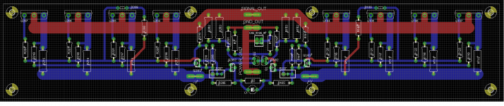
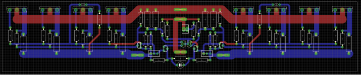
Try to move the gate stoppers closer to each mosfets.
My 2c
Now my question is, why?
Slightly shorter board would work with HeatsinkUSA part
If that board were slightly shorter, like 9.5 inches, it would be perfect with HeatSinkUSA part number E007, with is 10.08" W x 7.0" H x 2.875. That heatsink has a .3C/W thermal rating with natural convection. If low noise fans are used it should be big enough.
If that board were slightly shorter, like 9.5 inches, it would be perfect with HeatSinkUSA part number E007, with is 10.08" W x 7.0" H x 2.875. That heatsink has a .3C/W thermal rating with natural convection. If low noise fans are used it should be big enough.
I agree with massimo.
I was going to say it earlier, but I thought I might be being too picky.
There is a good chance they will be alright where they are, but there is a chance they won't be alright either.
Since it is a lot of work you may as well go for perfection.
When you get to the building stage, try and compare the differences in sound going from one pair to two pair to three ........ etc
Do you have a link to the post where that schematic came from or a #?
Wanted to make sure it works, but the effect should be the same as the solution with 2 resistors/2 caps.
Anyone here actually made a cascoded F5 and what where the results?
It works. That is what I have been using, as I preferred it over my original implementation.
For Nelsons original post see post#7965
Add the numbered components. Just about any bipolar devices
will do.
Last edited:
- Home
- Amplifiers
- Pass Labs
- F5 power amplifier