How critical are the values of the 220µF caps can I use 470µF?
22k and 220u have RC time constant of a bit less than 5 seconds - with 470u you'll have a bit more than 10 seconds.
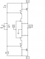
The RC time value defines time needed to charge the cap to approximately 63% of the nominal voltage (kind of a slow start). Also, since this is capacitance multiplier, the cap value defines the resulting capacitance i.e. the ripple voltage in output DC voltage.
For example, with 10k and 220u (IRFP240, 4700uF on output, current draw = 1.2A) I get the following results:
- input DC voltage = 24V
- input ripple = 200mV peak
- output DC voltage = 20.2V
- output ripple = 1mV peak
Last edited:
It's probably easier to cascode the Jfets with some bipolar
transistors.

How?

Hi
I will start building my F5 today and I need to check what the recommended fuse rating should be.
Nelson suggests using a T1.25 fuse if used with a 240v supply. I'm using a single 500VA transformer rather than the 300VA supplied in the production amp.
Would you recommend using a T2A fuse with this larger transformer?
Thanks
any of 1.2, 1.6 & 2A may work at full output power from the 500VA. try them all.
You will have to use a soft start to attenuate the start up transient current.
two CL60 in series for 240Vac may not be enough for the lowest of these fuses.
either add a third (getting expensive) or swap one CL60 to 10R+10R+10R in series (all 5W)
You will have to use a soft start to attenuate the start up transient current.
two CL60 in series for 240Vac may not be enough for the lowest of these fuses.
either add a third (getting expensive) or swap one CL60 to 10R+10R+10R in series (all 5W)
any of 1.2, 1.6 & 2A may work at full output power from the 500VA. try them all.
You will have to use a soft start to attenuate the start up transient current.
two CL60 in series for 240Vac may not be enough for the lowest of these fuses.
either add a third (getting expensive) or swap one CL60 to 10R+10R+10R in series (all 5W)
Great. Thanks Andrew
Banned
Joined 2002
Bear,
are you really suggesting that we don't fit mains fuses feeding the mains transformer?
I hope not.
Personally, id sacrifice it, if you can hear the difference between having a fuse in your system and not having one, then its pure and simple you are not enjoying your amplifier's sound.
Put it this way, will you still enjoy your amplifier if it burns your house down ?
Bear,fuses worry me... wonder about their sonic contribution(s)... but I may be crazy...
_-_-bear
I would look at this as an opportunity to upgrade your power supply.
Chokes in the power supply, regulation, line conditioning after the fuse could all be possible enhancements. I would look at Nelsons white paper for inspiration on PassDIY. Omiting the fuse is not an option.
Doug
I have a question about a power supply for a F5 amplifier.
In the F5 operators manual, theres is an example of a power supply, but Im not quite sure what the resistors in the schematic are for. The 2 x 2k2 resistors are bleeder resistors? And what are the 8 x 0R47 resistors for?
Furthermore, what about capitance for a supply, how much is needed? Planing on either building a F5 as is or a balanced version.
Whats the best way to make a single ended signal into a balanced? My pre amp doesnt have balanced outputs. Could you use a differential Op-amp? TI has a document about differential op-amps and they show how to use one for exactly that purpose.
Mmmm... DougL are you suggesting that i need to "upgrade" my supply? Nah. (best check my website, fyi) But thanks for the suggestion.
But anyhow, I am just raising the question of the effect of fuses.
Why not a circuit breaker?
How about multiple fuses in parallel?
How about a 10 amp fuse?
An 8 amp?
ok 7 amp... 5?
A 2.5 is a mighty thin bit of wire... so why not just use really thin wire all the time, everwhere?
_-_-bear
But anyhow, I am just raising the question of the effect of fuses.
Why not a circuit breaker?
How about multiple fuses in parallel?
How about a 10 amp fuse?
An 8 amp?
ok 7 amp... 5?
A 2.5 is a mighty thin bit of wire... so why not just use really thin wire all the time, everwhere?
_-_-bear
Neutrality, fyi your questions have been raised before in this thread, and a number of variations and approaches to the PS have been discussed... you might want to search or browse back into the thread?
Imo, the use of an opamp if you have a high resolution system might obviate the benefits of the F5's minimalist approach.
Any means including a single FET as a phase splitter out through a multi opamp "instrumentation" type configuration or a transformer could work.
Others might want to express other ideas or approaches, this is just me making noise...
_-_-
- Home
- Amplifiers
- Pass Labs
- F5 power amplifier