I'm about to embark on my second F5 build - the first one has been working beautifully now for a couple of years with no adjustments/hassles.
So I recently achieved a long term goal and snagged a second pair of Quad 57s - so I'm building this F5 to run the stacked quads. Trouble is I don't want to give up the sound I'm getting from the F5 with horns in the other room!! Some might say its boring to build the same amp again, but hey - it sounds good!!
I've almost all the parts, and some of Peter's boards (bought 2 sets waaay back), stealth diodes etc, so I'm just waiting on some PS caps. This time I'm going to use an alu head from an engine for the chassis/heatsink.
The only thing I think I might be short of is mica insulators - although I think I have some of the silpads knocking about.
Looking forward to starting again!
Fran
Do you have a link to the post where that schematic came from or a #?
Wanted to make sure it works, but the effect should be the same as the solution with 2 resistors/2 caps.
Anyone here actually made a cascoded F5 and what where the results?
I do not remember where but i am certain.
I have built a cascoded F5 with double SK1530/SJ201 outputs, 33v rails, biased at 0.85 Amp per device.
Thus, keeping the same dissipation per device as in the original and delivering 50w classA into 8 ohms.
Last edited:

Hi bob maybe you should look at my post #9580I do not remember where but i am certain.
.
I do not remember where but i am certain.
I have built a cascoded F5 with double SK1530/SJ201 outputs, 33v rails, biased at 0.85 Amp per device.
Thus, keeping the same dissipation per device as in the original and delivering 50w classA into 8 ohms.
I am planning to build a similar one. Can you please share the working schematic. I was originally thinking of just replacing the irfs with Toshibas, but would like to stretch myself with your idea.
Cheers.
Rail limits for cascoded F5
What do you think the rail voltage limitation would be for a cascoded F5 using BC556 and BC546? They are 65V parts.
What do you think the rail voltage limitation would be for a cascoded F5 using BC556 and BC546? They are 65V parts.
It works. That is what I have been using, as I preferred it over my original implementation.
For Nelsons original post see post#7965
way above any sane limit ;
you'll get much earlier driving limitation of input Jfet combo , considering that - wanting increased power output - you must in same time to increase both PSU voltage and Iq ; that , last one , demands multiple outputs ( think about max dissipation per device ) , that's why driving capability of input parts is limiting factor ;
going above doubling vertical pair of inputs , at least in my book , is just invoking old proverb - "don't use force , use a bigger hammer "
meaning - just make some really bigger amp
What VA rating are they?
If they are cheap you may as well get them (provided the VA rating is high enough). If the voltages are too high for this project you can always add the BA-2 mod to it on the output.
Edit: Will you be building separate monoblocks or a stereo chassis? What heatsinks do you have?
Depending on what you have you might be limited to 1A bias. If you go mono blocks then probably 2A. I would not exceed 40W per device.
Last edited:
So, im asking again, what are the driving capabilities of the 2 input JFET's, people have succesfully made 3 output pair F5's so 4 pairs might work as well. But would be nice to have some sort of confirmation on that before I spend a small fortune on PCB's.
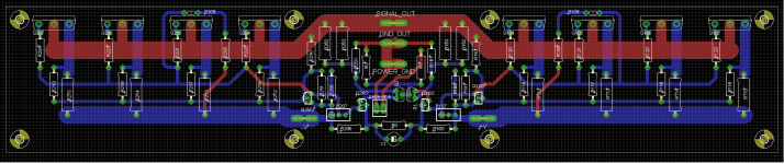
Optimized layout with gate stoppers closer to the FET's and moving of the input should be done soon.
Optimized layout with gate stoppers closer to the FET's and moving of the input should be done soon.
I am planning to build a similar one. Can you please share the working schematic. I was originally thinking of just replacing the irfs with Toshibas, but would like to stretch myself with your idea.
Cheers.
The toshibas have a lower Vgs.
So, potentiometers and their parallel resistors become 2K and 1K.
I have not used any thermistor neither limiters.
Though I am thinking again about thermistors because warm up time is quite long.
I'll try paralleleing two 4k7 thermistors (instead of one) and reduce the serial resistor to 500R.
Don't know if it makes a difference, but I would send output ground directly to 0V on power supply rather than sending it back to the pcb.
Someone else might like to comment about that.
I thought about that as well, but whats the reason/benefit for doing so?
So, im asking again, what are the driving capabilities of the 2 input JFET's, people have succesfully made 3 output pair F5's so 4 pairs might work as well.
I do not know the answer but you can still parallel input Jfets if necessary.
Don't know if it makes a difference, but I would send output ground directly to 0V on power supply rather than sending it back to the pcb.
Someone else might like to comment about that.
I thought about that as well, but whats the reason/benefit for doing so?
I you build a monoblock you have a choice of where to locate the main Audio Ground. It can be on the PCB or at a location that is central between the speakers terminal, the Pgnd of the PCB, the Signal Ground of the PCB and the PSU Zero Volts.Current flows from caps through speakers. So it's logical to wire the speaker return to PSU.
It prevents high current from flowing through the ground wire from PCB to psu.
But, do not put that main Audio Ground at the PSU.
Where ever that main Audio ground goes, then determines where all the other grounds MUST return to get their reference voltage.
If the speaker return goes to the PCB then ALL other grounds must also go to the same POINT.
If you build a multichannel amplifier instead of a monoblock then you cannot put the main Audio Ground on each PCB, nor at the PSU zero volts.
Choose a location roughly at the centroid (middle) of the speaker returns, the PSU Zero Volts, the PGND of the PCBs and the Signal Gnd of the PCBs. This central Ground must be the reference for all other grounds.
- Home
- Amplifiers
- Pass Labs
- F5 power amplifier