Yes the DAC (CS4398) is transformer coupled,what to do about the inductance?
I have used the interconnects with my Benchmark DAC 1 whithout any problem(Heat).
I have no idea, but I dont think you can remove inductance
Will a series cap do anything ?
But probably not
It doesnt in a speaker xover
You say your trafo output have 1Kohm in series and 2.2nf to ground, as I understand it
How does that work/couple with the F5 input, 1Kohm/100Kohm
The paralel 2.2nf might worry me a bit
But I really dont know
DC related or what
What will happen if you remove the 1kohm/2.2nf on trafo output ?
Might it be a low pass filter to prevent passing on high FR problems, and that it really dosnt work well
Because of the exstreme simplicity F5 might be somewhat sensitive to any ground coupling, but I dont know
But maybe be a bit careful until someone with knowledge have evaluated this
Last edited:
cool beans guys, thanks. i've never had to deal with this amount of heavy thermal management before.
are you suggestion that i have a screw loose") ?
?
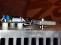
good point, i can see where the base is restricting rising air flow.
... and maybe one more screw in the middle too... or am i wrong?
Cheers!
are you suggestion that i have a screw loose
? If not he can always open up the mounting bases by sawing 1" off and put some real feet underneith.
good point, i can see where the base is restricting rising air flow.
Last edited:
good point, i can see where the base is restricting rising air flow.
I will estimate that it may increase or decrease efficiency by maybe +/- 20%
But its a wild guess and depends on design
But if you control and increase up upwards airflow in the "tunnel" you have between your heatsinks, it might be very effective as a "pull motor" fore outside flow
Funny to think that even to close in the heatsink may improve airflow and effectiveness, if it can "breathe" properly
Maybe some kind of cooling fluid inside the bottom of heatsink could be interesting if it would be "dragging" more fresh air
But I suppose theres other simpler ways around it
One thing
To have the mounting surface machine planed
If theres any possibility to have it done, do it
Though, I have no idea how much the heatsink bents when its hot
But now I think Im about to loose it, and just rambling too much
Last edited:
Even though heat dissipation won't increase proportional to the size of the sink it isn't a bad idea to get one sufficiently large to build a balanced version. Also, some people mount their transistors to copper heat spreaders and mount the spreaders to the aluminum sink to increase thermal conductance in order to make better use of a large heatsink. The copper conducts heat more efficiently than aluminum and the large contact surface between the copper and the aluminum allows for a more effective usage of the whole heatsink. Of course, this isn't really necessary but the more heat you can dissipate, the more you can bias your amp which will give noticeable improvements in sound.
Thanks to all who ventured an answer, and especially Brian for reference to using a heat spreader. That's new to me and will investigate futher.
especially Brian for reference to using a heat spreader. That's new to me and will investigate futher.
I have heard some suggest to use copper between devices and heatsink because of better sound properties of copper, or even better use silver, well whatever
Others claim the old style isolators sound better than modern materials, who knows
The ultimate way to use the copper "heat spreader" is supposed to work best if you mount devices on copper without any isolators
By this its possible to mount an even bigger and better heat conducting isolator between copper plate and heatsink
It might be pretty risky in terms of shorting through the mounting screw
Honestly I dont believe theres much advantage due to the added complexity and connections, its probably just a winn and loose game
I believe in proper dimensioning and smooth mounting, concervative and careful attention to complete design, thats all it takes
Last edited:
What IS the recommended heat sink per channel people are using here? I see the Pass article specifies 8"x6" w/ 2" fins, 2 per channel. I see a few here only using one slightly larger for the whole amp. I just want/need 1 heat sink per channel. Is 8"x10" w/ 2" fins acceptable for each channel? I want as much heatsink as is beneficial. Have thought of 10" x 12"x2", one on each side, one for each channel, but man the cost goes up! Should I just go ahead with 10x 12x2? I figure I need at LEAST 2 in the 8x10x2
for a stereo amp, right? Please advise! I would also like enough in case I get the guts to do a balanced version.....Thanks!
russellc
Have thought of 10" x 12"x2", one on each side, one for each channel, but man the cost goes up! Should I just go ahead with 10x 12x2? I figure I need at LEAST 2 in the 8x10x2for a stereo amp, right? Please advise! I would also like enough in case I get the guts to do a balanced version.....Thanks!
russellc
Last edited:
Banned
Joined 2002
Anyone know where my son put my micrometer? I found the DMM and the socket wrenches.
outside, using them as a crescent wrench ?
Anyone know where my son put my micrometer? I found the DMM and the socket wrenches.
Try under the bed, in a shoe, or my favorite, the toilet.
I have no idea, but I dont think you can remove inductance
Will a series cap do anything ?
But probably not
It doesnt in a speaker xover
You say your trafo output have 1Kohm in series and 2.2nf to ground, as I understand it
How does that work/couple with the F5 input, 1Kohm/100Kohm
The paralel 2.2nf might worry me a bit
But I really dont know
DC related or what
What will happen if you remove the 1kohm/2.2nf on trafo output ?
Might it be a low pass filter to prevent passing on high FR problems, and that it really dosnt work well
Because of the exstreme simplicity F5 might be somewhat sensitive to any ground coupling, but I dont know
But maybe be a bit careful until someone with knowledge have evaluated this
I will try to remove the 1k/2,2nf and try a 18pf across R10 instead of 2,2nf.
I thought Nelsson could answer this..but no sign of him..
thermistor placement?
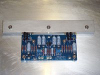
just wanted to get a concensus on where the thermistors should be placed. the way i have my board and mosfets attached to the heatsink give me two options. hopefully my photos can aid in determining what i'm talking about. it's hard to get a clear photo that is large enough!
the options are:
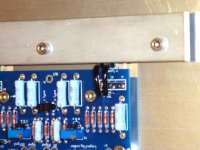
1. thermistor is in contact w/ the mosfet and 2 of its pins. it also touches the strip of aluminum i am using to clamp the mosfets to the heatsink. it seems to be electrically isolated still, but touches several pieces and is kind of wedged in there. no pressure is on it, but it's a snug fit (but still loose enough to slide in there easily). i have the leads covered with insulating sleeves. this is how i currently have things set up.
2. i could also position the thermistors "above" the circuit board and they could sit next to the aluminum clamping strip. my concern with this is that they won't be in direct line of the mosfet package and the aluminum strip might provide some thermal shielding so the thermistor doesn't have a good idea of what's going on.
any ideas?
just wanted to get a concensus on where the thermistors should be placed. the way i have my board and mosfets attached to the heatsink give me two options. hopefully my photos can aid in determining what i'm talking about. it's hard to get a clear photo that is large enough!
the options are:
1. thermistor is in contact w/ the mosfet and 2 of its pins. it also touches the strip of aluminum i am using to clamp the mosfets to the heatsink. it seems to be electrically isolated still, but touches several pieces and is kind of wedged in there. no pressure is on it, but it's a snug fit (but still loose enough to slide in there easily). i have the leads covered with insulating sleeves. this is how i currently have things set up.
2. i could also position the thermistors "above" the circuit board and they could sit next to the aluminum clamping strip. my concern with this is that they won't be in direct line of the mosfet package and the aluminum strip might provide some thermal shielding so the thermistor doesn't have a good idea of what's going on.
any ideas?
Attachments
Honestly I dont believe theres much advantage due to the added complexity and connections, its probably just a winn and loose game
I believe in proper dimensioning and smooth mounting, concervative and careful attention to complete design, thats all it takes
KISS, I get it.
Ha, ha!are you suggestion that i have a screw loose
No, no... it was mint as friendly suggestion!
The proof is below photo!
BTW:
my A-class Death of Zen upon Rod Elliott's PCB with L bracket 6x40x45/200 mm.
Maybe now...?The proof is below photo!
Attachments
Maybe now...?
i got it now. those heatsink aren't going anywhere. i know my heatsinks will need to be reinforced.
Last edited:
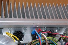
yes they are. i got sample sheets a while ago of both the K-10 and Q-Pad 3. i simply cut some squares out of the K-10 to use. i had hoped to use mica and grease as everyone seems to say they work better, but i could not locate TO-247 pads anywhere easily. since i am getting anxious for sound and i had this lying around, i figured it should be sufficient
let me know if you want a square as i have plenty left and could drop some in the mail for you.
let me know if you want a square as i have plenty left and could drop some in the mail for you.
enochRoot,
are those Bergquist K-10 pads isolating the MOSFETs? i realized last night that i don't have any TO-247 pads. i also found some TO-3 rectangular mica from Mouser that could be trimmed down as well.
Last edited:
enochRoot,
are those Bergquist K-10 pads isolating the MOSFETs? i realized last night that i don't have any TO-247 pads. i also found some TO-3 rectangular mica from Mouser that could be trimmed down as well.
TO-247 Transistor Mica Insulator,Insulation sheet, x 50 - eBay (item 250541364333 end time Jan-01-10 08:46:42 PST)
- Home
- Amplifiers
- Pass Labs
- F5 power amplifier