Regarding output mosfets, probably go 4 or 6 pairs per channel
You've already calculated the equivalent gate capacitance of parallel vertical MOSFETs ?
You gents are forgetting that the 3-pair F5 by Mr Walton uses Lateral MOSFETs.
If you number up the equivalent gate capacitance of 3 J162/K1058 pairs you end up with an entirely different figure than the one for Verticalos.
I could post a Jean Hiraga solution for your 6-pair F5X right away, but that would somehow spoil the fun.

Attachments

Last edited:
I was "playing"around with a home modded DAC conencted to the F5,and it made som weird noises (higs and lows) when starting and shuting down,maybe that was the caus of it?Oscillation on both channels?
Cant think of anything else,have worket fine since I maid it maybe a half year.
I can play with it now to,"only" get a distorted sound..
Any way I ordered some new resistors..
Jacco, ofcourse you are right, I suppose
We have been around that issue more than once, with repect of drivin multiple outputs
And it indeed was suggested that the easier driven Toshibas would be a good choise
And now we know it only concerns certain samples
I remember when looking at J201/K1530, it was clear that the available Y-version had twice the Vgs than other version, which made mw think twice
Finding the J162/K1058 with 0.5/0.8 Vgs meeting the criteria much better, made me take the chance with this
Or else I dont think I would have
And yes, we tend to forgets such "small" facts along the way
Its good to be reminded
Also fore those who may rush into this without the needed experience
I thank you fore teaching this "simple" stuff
Ryssen, Nelson have said several times that F5 can be very sensitive to "wrong" souces connected, cables etc, and its said in manual
Sounds like the problem you have with your CD player might very well have caused oscillation, and overheating
R9 and R10 are there fore that reason, according to F5 manual
You have these in your curcuit ?
Last edited:
You've already calculated the equivalent gate capacitance of parallel vertical MOSFETs ?
No, I have already built and tested it.
Runs like a dream.
Only one more decision to make, cascoding Jfet or not
would be nice to figure out this option- mostly because there are so many higher output transformers around to be used!
Yes they are there.R9 and R10 are there fore that reason, according to F5 manual
You have these in your curcuit ?
Edit:I am using he DAC with the F3 now and its works fine,quess I just turn the "stero" in the right order..
Last edited:
No, I have already built and tested it.
Runs like a dream.
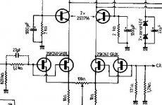
Ciss = Cgd + Cgs
Crss = Cgd
Source follower : Cgs remains constant, as in need not be charged/discharged.
Gain of vertical mosfet in source follower thingy = 0.9
Miller effect : Cm = C (1 - Av)
The effective gate capacitance of the output stage is greatly reduced by the stuff above.
(Ciss/Coss/Crss numbers are mainly meant for switching purposes)
Still, if you put 3 power MOSFETs in parallel the drive input capacitance will be 3 times as large.
Lateral MOSFETs in parallel have a combined effective gate capacitance that is much less than parallel vertical MOSFETs.
Effective gate capacitance sources at diyA ; Mr Charles Hansen, Mr Cordell, Ilimzn, and of course the Ranch Guru with his folding deck chair.
http://www.audioxpress.com/magsdirx/ax/addenda/media/moore2355.pdf
Beefed up F5 with verticals in parallel requires more drive current.
Place your bets, rien ne va plus : Double or Nothing
Attachments
would be nice to figure out this option
Yes, Thanh and Juma did nice work on this subject, not very long back
But couldnt agree whether to connect cascode base ground resistor through Jfet ground resistor, or directly to ground
And Nelson have stated that there is no other aswer than to try both
And that seems to where we are at the moment
Thanhs results will be interesting
Im sure he will have some results before I even get started
")
Regarding whether where to connect cascode ground resistor
How about making the Jfet ground resistor into 2 series ditto
And connect cascode ground resistor to the midpoint of those
Sort of half of both worlds
I suppose the only differense is isolating the cascode ground cap
In speaker xo I have tried similar with some positive result, but introduce some phase issues
Probably nothing to do with this
Or is it similar, and related to the "Q" of curcuit, ie damping/control
Last edited:
Still, if you put 3 power MOSFETs in parallel the drive input capacitance will be 3 times as large.
Lateral MOSFETs in parallel have a combined effective gate capacitance that is much less than parallel vertical MOSFETs.
You are forgetting that Laterals have much lower Yfs.
It would be nice to have your cake and eat it but in this case it is not that straight forward.
You should also look at the F4.
You are also forgetting I have already built this and it performs on the oscilloscope better than anything else I have tested in the past.
Maybe Neslon will design some fets with the capacitance of laterals and the transconductance of the SiC power Jfets.
For me the maths/physics is irrellevant if the thing works, which has been the case for me.
Last edited:
Tinitus, We are very lucky that Nelson gave us his F5 schematic.
I think our first building has to be the regular F5. At least as a reference for further trials.
Yes indeed
It is I believe also the best documented, and probably fore a reason
But the outcome of a comparison between a mod version and original may just rely on connected speaker, or maybe even simply just the music
If you do happen to have the optimal speakers fore original F5 Im sure it will take the lead
Last edited:
I was "playing"around with a home modded DAC conencted to the F5,and it made som weird noises (higs and lows) when starting and shuting down,maybe that was the caus of it?
Cant think of anything else,have worket fine since I maid it maybe a half year.
I can play with it now to,"only" get a distorted sound..
Any way I ordered some new resistors..
Hi,
Can someone tell me what parasitic oscillations sound like? Is it something obvious or more subtle that needs to be measured on an oscilloscope? The F5 manual mentions oscillations as the reason for including the gate resistors R9, R13&R14. I've been running sans R9 because the manual says "depending on the source" indicating that not all sources will cause problems and I'm using a lightspeed attenuator, which is essentially a resistor and it seemed redundant to have R9. I've not noticed any problems. I was assuming that any oscillation would be readily apparent, but one gets into trouble when assuming so I'm asking.
I have the weaker laterals
Used as single pairs I would have to easy on the voltage and bias, I guess
Doesnt sound to me like a good option
DIY is meant to be fun. So if you have these laying around unused, give it a go.
You can always put in the IR devices on the other channel and do a comparison
- Home
- Amplifiers
- Pass Labs
- F5 power amplifier