2SJ76 ringing a bell ?

It is bloody hot working outside, time for a break and a glass of coke.
Yes they are very nice devices indeed.
I tried to get hold of some recently but did not have any success.
Back to work.
I will be back later.
Last edited:
...I'm not sure whether I want 50 ohms at the end of the day or 75 ohms for feedback. ...
Of course, that was my intention too. So 2 Watters are quite enough because if you choose higher resistance the dissipation on them will be lower (the current through them will be smaller).
btw, take a look at these small fellows, very low miller and input capacitance
http://docs-europe.electrocomponents.com/webdocs/0791/0900766b807912cb.pdf
http://docs-europe.electrocomponents.com/webdocs/0791/0900766b8079172c.pdf
http://docs-europe.electrocomponents.com/webdocs/0791/0900766b807912cc.pdf
http://docs-europe.electrocomponents.com/webdocs/0791/0900766b807910f6.pdf
http://docs-europe.electrocomponents.com/webdocs/0791/0900766b807912cb.pdf
http://docs-europe.electrocomponents.com/webdocs/0791/0900766b8079172c.pdf
http://docs-europe.electrocomponents.com/webdocs/0791/0900766b807912cc.pdf
http://docs-europe.electrocomponents.com/webdocs/0791/0900766b807910f6.pdf
 )
)As a builder of a cascoded F5, i will be happy to share my experiment.
I have used Cviller V2 boards. These boards are nice and easy to use.
The Cviller blog about it is also nicely informative.
I have used a 25v trafo which gives 33v rails allowing to double the F5 class A power.
Twin matched outputs are biased at 1.85 A each, which results in the same dissipation / output device as per the stock F5.
I used 400mm x 100mm x 80mm heatsinks as i had them on hand.
These don't get too warm for the actual winter time. Let's see in summer.
Trafos are 300VA per channel.
There is no hum with only 33000 uf / rail / channel, but i plan to increase at 60000uf when boxed. I use CRC configuration.
I have used no limiters neither thermistors for now but the warming period is about 1 hour and a half. So, i plan to incorporate thermistors in order to lower this duration.
It was as easy to build as the stock version .
It sounds as sweet as it also.
Last edited:
New PCB
I etched a new board with the caps going to ground. I'll start with the IRFP outputs and then switch to the Toshibas. Two output devices per side of the circuit (eight MOSFETs total).
For those who have a cascoded F5, can you share the outcome vs. the stock F5? Is there a difference in sound? What rail voltage did you use? What voltage dividers?
Hopefully the outcome is sweet enough to sell off the Balanced F5 parts I have - Futaba Fukushima MCP74s in 0R18, 0R22, 0R47 and 1R0. They were incredibly difficult to get in the United States. I'll hang onto one set in case the Balanced thread ever produces a working amp.
I used equal resistors for cascode dividers.
I used Toshibas and 0.47 ohms source resistors.
I did not implement the Euvl 4 ohms trick in ( matched) Jfet input stage.
I wanted it simple as i think that splitting hairs into pieces will bring marginal differences in sound.
Results:
Sound is not much different from F5.
Or my ears aren't sharp enough.
Any answer you will get about this will be subjective and you have to build it to know exactly.
Edit: The main improvement is power.
Last edited:
Thanks for this assessment, much appreciated! Just so I am clear, does "twin matched outputs" meanTwin matched outputs are biased at 1.85 A each, which results in the same dissipation / output device as per the stock F5.
you only used two outputs per channel, or four? Thanks for your input on this version of F-5. Were there any other deviations from standard F-5 in building this version?
Thanks in advance,
Russellc
Last edited:
Two pairs per channel of course as you need to dissipate twice as much.does "twin matched outputs" mean
you only used two outputs per channel, or four?
The last thing that differs from the stock version are the pots and R3 R4 which halve their value when using toshibas.
My mistake about biasing .
Correct is 0.85A per Output device. ( not 1.85)
Last edited:
I have a stupid question. Would this thread be more appropriately titled: High Power F5 Variants? After reading http://firstwatt.com/pdf/art_sweet_spot.pdf, I wondered if cascoding the outputs might increase the performance a bit at the cost of some power and higher complexity. Has anyone tried this on an F5?
Doug
Doug
Could you please elaborate a bit?with cascoding - output swing is limited
")
Doug
What you can do in a day...
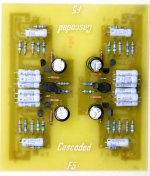
Here are the redesigned, re-etched, rebuilt "Cascoded F5"s (still minus thermistors and Mosfets). These caps reference ground. For the moment, I'm using an equal voltage divider (4.7K ohms, 4.7K ohms) on each side.
I'm moving tomorrow and Tuesday, realistically, I won't have a chance to try this until the weekend at best.
Perhaps others can post their progress until I'm back in action.
Attachments
Yes, I know. I'm mounting the Mosfets remotely. This board is for testing, when I go for the final version, I expect to have pairs of outputs on each leg of the circuit (8 Mosfets in all). To limit problems, I'll put the source resistors on the legs of the Mosfets as well as relocating the gate resistors. Mounting the PCB to the heatsink has always seemed like a limiting step. I like the idea of exchanging amp boards while leaving the Mosfets mounted and in place.
I have a set of etched "Balanced" boards, as well as all the parts to build. I couldn't get simple answers on the power supply, so the boards sit...very frustrating considering the forum is supposed to be a place to get help from one's comrades.
I have a set of etched "Balanced" boards, as well as all the parts to build. I couldn't get simple answers on the power supply, so the boards sit...very frustrating considering the forum is supposed to be a place to get help from one's comrades.
hey NYCOne
I suppose you are aware that you have 2 channels together on one board, and probably made for balanced
well, in terms of heat, its not good to have both channels share the same heatsink
- Status
- This old topic is closed. If you want to reopen this topic, contact a moderator using the "Report Post" button.
- Home
- Amplifiers
- Pass Labs
- F5 Cascoded - an alternative for my interest in the Balanced F5