I meant on output gate's protective zenners , preventing excessive Ugs
you need them .
You are quite correct, my F4's have the zenners fitted. I left some of the bits out of the circuit for clarity, I was also being lazy
 I should know better.
The circuit is really only to show the current mirror/level shifter mod.
Questions about using higher voltage transformer.
Hi
I am building a stereo F4 (r0 6/4/07) with 20v dual secondary transformer(400va). Since I have higher voltage rail(+-26.5v after rectification and filtering), I increased R5 and R22 to reduce the voltage for JFETS. I changed 1K -> 2.4K and 750R -> 2.2K, then I get about +-20V for JFETS with everything connected.
My questions are:
1. When you use 18v secondary transformers, what voltage do you get for JFETS?
2. When I change the values for R5 and R22, do I need to adjust the bootstraping resistors(R24 and R25) also?
3. Is there anything else I need to consider to use higher voltage rail?
Thank you.
Thank you for the quick response.
When I measure the voltage going into the JFETS, it is +-25.7v which I think is a little bit over the maximum and I wanted to bring it down to around +-20v.
I have studied the schematics and read the postings in this forum, but I still do not understand the bootstraping circuit. If C3 and C4 were grounded, they would simply form a RC filter for JFETS with R5 and R22. But since C3 and C4 are connected to the output with resistors, I GUESS they provide some sort of feedback from the output signal. If the bootstrap network is using feedback, do values of R24 and R25 not determin the feedback amount?
Thank you
According to datasheet IRFP240 has transconductance min 6.9S and IRFP9240 has 4.2S. Why not to use different value of source reistor to compensate? For example 0.47R with IRFP240 and 0.22R with IRFP9240.
If you measure a lot of devices, you'll find that transconductance seems to be related to the threshold voltage (Vgst) so I wouldn't take the manufacturer data sheet number and use it as gospel.
Early on in the F5 thread, Nelson said that the source resistors for the output MOSFETs could be played around with to lower THD% Increasing this resistor has the effect of lowering transconductance at high current --- you should get Bob Cordell's book "Designing Audio power Amplifiers" -- it's on page 233.
I have read that page. He uses 0.15R for IRFP240 and 0.22R for IRFP9240, shouldn´t it be vice versa?
but you can always do better
That means that there is some benefit of more current drive? Less THD or something else?
I know certain toobz pre with excellent psu that makes a sweet combo for naked F4 if you are interested. Beats any SS pre I have tried, but I have not tried them all.
Sure, why not. Can you post schematics or link?
.....which I like more - killer PSU and high xconductance toobz
Any chance of a sneak peek ZM

not much presented on line
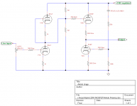
just old WOT , which I made ages ago - WOT preamp and battery charger
several musings ( some as dedicated line stages , some as dedicated gain stages ) are on Baby Diya , but I'm too lazy to present them in comprehensive way
in any case , mix'n'match of sand and glass
just old WOT , which I made ages ago - WOT preamp and battery charger
several musings ( some as dedicated line stages , some as dedicated gain stages ) are on Baby Diya , but I'm too lazy to present them in comprehensive way
in any case , mix'n'match of sand and glass
- Home
- Amplifiers
- Pass Labs
- F4 power amplifier