That is completely intentional.
N channel parts are only dissipating 25W.
I intentionally wanted more current going through the N channel parts and less on the P channel parts as a way to more closely match the temperature coefficient between N and P channel parts.
Fairly intelligent if I do say so myself. Hahahaha
Playing with CCS will come later though on a completely different design, not this one.
Last edited:
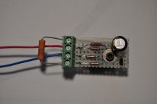
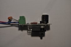
Here is a quick way to add a CCS without having to modify the PCB. Put the CCS components on a small piece of perfboard and mount with the same screw that attached the FET to the heatsink.
I won't be doing that on this design, later I will do it on a different design.

No need for bias stabilisation.
Just catching up with the latest on this thread...
OK, so no need for bias stabilization from a thermal perspective but what about current sharing between the devices? Is matching the devices sufficient to avoid any current hogging?
I meant on photo = what's missing .....
Ok.
If people want to try it out it's important to have big heatsinks, use keratherm etc to minimise delta T between turn on and at full operating conditions.
Not absolutely mandatory but it will significantly improve the delta bias current between start up and operating conditions.
Obviously matching is important, the devices are matched to within 3% of each other I can explain how I did this. That is the current through each device is not more than 3% different from each other at the bias point.
Not too difficult.
Last edited:
what about current sharing between the devices? Is matching the devices sufficient to avoid any current hogging?
Yes matching is sufficient but I think I would need to explain my procedure, of how I do it.
In my circuit current through each mosfet does not differ by more than 3%.
Hockey pucks are for sissies.
Hahaha

Implying real men match MOSFETs?

- Home
- Amplifiers
- Pass Labs
- F4 Beast Builders