Cheating on Cornu...
I was contemplating about cheating on Cornu...
Or call it "Cornu sans the spiral..."")
In fact, the main idea was about making the most effective use of a pair of drivers that are still sitting in a box: CSS 125 FR.
At first I was very enthusiastic about building the Spiral Cornu, but the enthusiasm subsided as I realized that this driver is not really suited for horn loading...(so no Cornu for them)
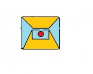
But...how about building the "Cornu-like" box which will in fact be the bass-reflex design, but with the ports expanding into mouths, not much unlike the Calhoun", but in Cornu style
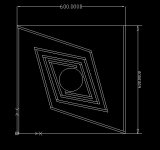
I tried to make a rough sketch. A reflex box with the ports expanding on both sides. The area filled in yellow serves no purpose. It could be entirely cut-out or filled with something...
I was contemplating about cheating on Cornu...
Or call it "Cornu sans the spiral..."
In fact, the main idea was about making the most effective use of a pair of drivers that are still sitting in a box: CSS 125 FR.
At first I was very enthusiastic about building the Spiral Cornu, but the enthusiasm subsided as I realized that this driver is not really suited for horn loading...(so no Cornu for them)
But...how about building the "Cornu-like" box which will in fact be the bass-reflex design, but with the ports expanding into mouths, not much unlike the Calhoun", but in Cornu style
I tried to make a rough sketch. A reflex box with the ports expanding on both sides. The area filled in yellow serves no purpose. It could be entirely cut-out or filled with something...
Attachments
Vix,
Why do you say the CSS FR125 is not good for the Cornu or horn loading? If you think you need low Qts, that is a myth from days past when high impedance amps were the norm. The FR125 will work fine in a Cornu. The box you drew is a Big Vent Reflex. It will need a real design from a simulation otherwise you are just guessing and the outcome will probably not be as good as a Cornu. The BVR needs a pretty big volume chamber so your box will be much larger (or use the volume on outside of the BVR "horns" to get more volume. BVR's do add gain to the BR output but at the expense of pipe resonances and coloration.
Why do you say the CSS FR125 is not good for the Cornu or horn loading? If you think you need low Qts, that is a myth from days past when high impedance amps were the norm. The FR125 will work fine in a Cornu. The box you drew is a Big Vent Reflex. It will need a real design from a simulation otherwise you are just guessing and the outcome will probably not be as good as a Cornu. The BVR needs a pretty big volume chamber so your box will be much larger (or use the volume on outside of the BVR "horns" to get more volume. BVR's do add gain to the BR output but at the expense of pipe resonances and coloration.
To X and Cal, thx again guys for the inspiration and inputs last month. November was busy closing out our fiscal year at work, elk hunting for a week (actually just camping wearing funny camo outfits as there were no elk to be had), a few days in Mexico, Thanksgiving, etc.
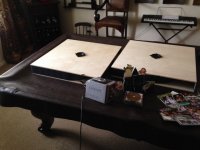
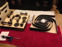
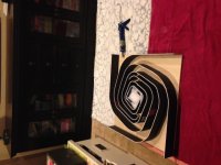
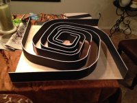
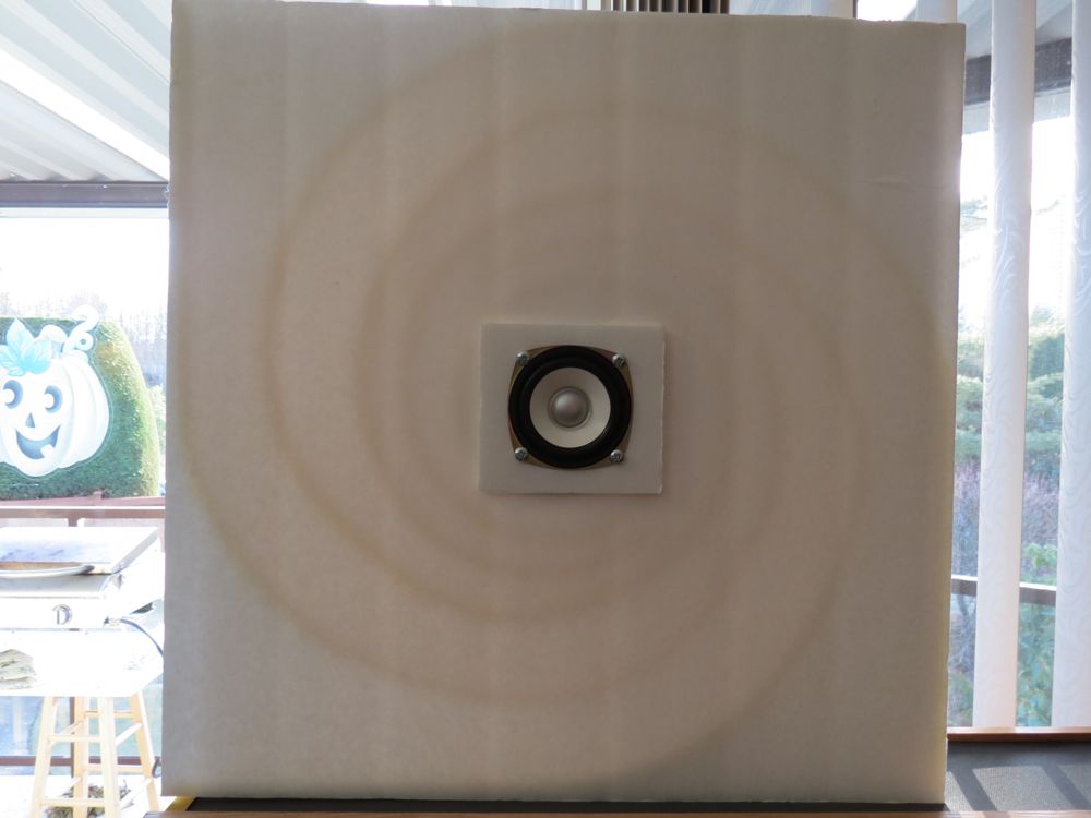
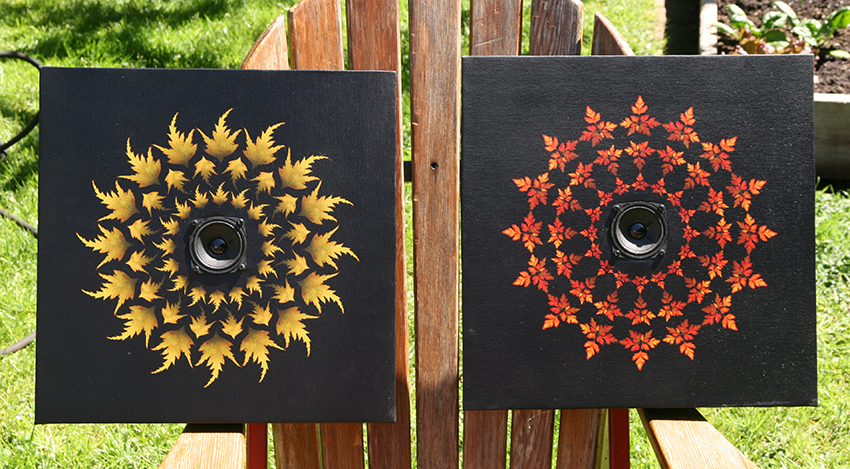
I finished up the speakers and got to install them for my friend's new venture. I love the detail and clarity these bring out, had a great time setting them up the morning of 12/5 and having them be part of his party later that night. Easily filled the room with great audio and was a conversation topic throughout the night.
I'd consider these "prototypes" after now having done my first run of these. Time will tell if I do more (the ideas to improve build construction, better materials, resonance elimination, etc. are all there!!)....but very glad I did something a bit bespoke instead of just picking up something from Craigslist or BB. Much more time-consuming than I'd initially estimated but aren't all projects like that?
No pics (today) of the grills with the screen-printed logs I did - just forgot to snap pics of those but they turned out much better than I'd ever hoped they would - really was a nice touch.
Go for it if you think you want to give these a shot....they truly do sound 100X better than what the little drivers seem to be capable of producing. Pics below (you can see them hanging in the background of the last pic if you look close).....take care!!!
Attachments

Last edited:

Congratulations tli!
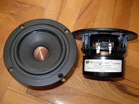
What driver did you use and what is the size of the speaker? Those look like Faital Pro 4FE35's?
Nice party! Never seen anyone hang them up so high.
Good eye, those are indeed the 4FE35's (you recommended them back when I started out in early November, very happy with them).
The installed location (height) really worked out well for the office setting. They were intended to service background music but really do lend a lot of detail when there aren't 75 people milling around and you can spend time doing a little critical listening from about 25' away. Quite a few members of his staff were doing a little listening with me during the morning and were all really impressed. Fun stuff!
Cabs are 29.5" x 29.5" (cuts worked out that way based on what was on hand at the local supply store), foam board is ~3.5" tall (from memory).
Summary of what I've read
I've read this thread from start to finish. I don't remember everything, but here's a summary of what I believe are the main points. Before I start building anything, can some kind person let me know if I've misinterpreted anything?
The Cornu spiral speaker design’s main benefits are:
The main disadvantages are:
The name Cornu is a misnomer
A passenger in railway carriage travelling along a curved part of the track will experience a centripetal acceleration towards the inside of curve. If the curve has a constant radius (i.e., is an arc of a circle), and it exits onto a straight section of track that is tangential to the circle, the acceleration will terminate abruptly and will be felt by the passenger as a jerk. Cornu spirals avoid this jerk by reducing the radius of the curve gradually on entry and increasing it gradually on exit. They are named after an engineer called Cornu (hence the upper-case C); the similarity between Cornu and the word for horn in many Romance languages (corne (Fr), corno (It), cuerno(Sp)) is coincidental.
Furthermore, Cornu speakers do not, in spite of their name, employ a Cornu spiral, as the path that a sound wave follows is less important than the rate at which its cross-sectional area changes as it progresses. In fact, the speakers include a number of modified exponential horns.
Design
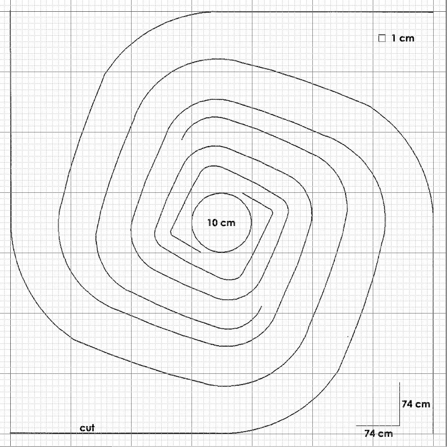
The "spiral" in the original design is mostly made up of straight sections. There is an alternative smooth-spiral design. The designs can be scaled up or down to accommodate different drivers. The 70 cm (29”) version shown in the image is appropriate for drivers with an 11cm (4.5”) diaphragm. It should be scaled down to 60cm (24”) for 7.5cm (3”) drivers and up to 90cm (36”) for 6” drivers.
Note that both of the above designs are labelled 74 x 74 cm (29” x 29”), but the layout of the underlying grid and the 10cm central section both suggest that the actual dimensions of the speaker are 70cm x 70cm (27.5” x 27.5”). Since it is expected that the design will be scaled up or down according to the size of the driver, this inconsistency does not seem particularly important, but it might be confusing to a newcomer.
The total throat area at the exit from the cavity behind the driver should be somewhere between 0.5 and 1 times the driver’s diaphragm area, Sd. That is, if a standard Cornu design (with two channels exiting from the cavity) is used, each of those two channels should have a throat area of 0.25 to 0.5 times Sd¬. For an Alpair 10 driver with an Sd of 88.25 cm2 and a channel with a throat width of 2.5cm (as on the original plan), the channel walls would be between 8.8cm (3.5”) and 17.7cm (7”). Making the channel walls higher would necessitate in narrower throats, which would attenuate the bass.
J.A. Dinsdale’s 1974 Wireless World article about horn design has an alternative formula that produces a similar but not identical result.
For a given cutoff frequency, f, the throat area, St is given by
St = 2 π f V / c
where V is the volume of the cavity
c is the speed of sound (340ms-1)
So for a cavity with a radius of 7cm and a height of 17.65cm, and a cutoff frequency of 100Hz, the total throat width would be 2.8cm, so each of the two throats would be 1.4 cm wide. This is at one end of the range given by the with the “make the throat area between 1 and 0.5 times Sd” rule. It is thought that the sharp turns help in filtering out high frequencies from the bass channels, but smooth exponentials have also been used successfully.
It may be beneficial to place a conical 45-degree reflector behind the speaker to prevent reflections from the back wall from emerging via the speaker cone.
Reducing the height of the channel walls, without changing the width of the throat, reduces the amount of bass boost. Reducing the length of the channels reduces the bass extension. Since the Cornu design has a very large expansion ratio, the bass boost is very high; it may therefore be sensible to keep the channel height towards the lower values suggested by the 0.5 to 1 times Sd rule.
In post 1299, it is suggested that it may be beneficial to add an extra chamber in front of or behind the main cavity to even out the mid-bass performance. It should expand the volume of the current chamber by 4x to 5x. For the speaker mentioned above, with17.65cm high channel walls and a chamber diameter of 14cm, the chamber volume would be 2717 cm3, and the expansion chamber would therefore have a volume of between 2717 x 3cm3 = 8151 cm3 and 2717 x 4cm3 = 10868cm3. This would correspond to a 4cm (1.5”) deep square box between 45 cm (18”) and 52cm (20.5”) on a side.
It may also be beneficial to add a short horn (11 cm to 22 cm diameter over a distance of 10cm, say) to the front of the driver to achieve a balance between the bass and treble, compensating for the large amount of bass boost produced by the exponential horn.
The two previous paragraphs suggest the possibility of recessing the driver within the cavity, increasing the size of the expansion box at the rear of the speaker to occupy the full X and Y dimensions and adding a front-loaded treble horn that fit within the body of the speaker. It might be necessary to modify the throats of the bass horn slightly to maintain their area.
It may be beneficial to stuff the cavity and a short section of the channels with an acoustic absorber to attenuate the bass so that it balances the higher frequencies. Fitting the absorbent material into a “sock,” and attaching strings to the sock that you can pull from the centre and from the horns makes it possible to pull the experiment with the amount of stuffing.
Construction
Channel walls are most conveniently made of foam core material such as picture framers use for backing on watercolour paintings or prints. It is light, easily bent, easily glued, and comparatively cheap. Plywood and mdf are significantly inferior for this purpose.
The preferred method of construction is to hot glue channel walls to the back baffle, following the pre-marked spiral path, from the middle to the outside edge, taking care to ensure that the junctions are sealed. Hot glue grabs well in a few seconds and allows a short time for adjustment of the channel walls. It helps to pre-form the foam core by bending it around some convenient edge, such as a counter-top, and also if slits approximately 3mm (1/8”) apart or less are cut on the inside faces of small-radius curves.
It is not feasible to attach the front baffle with hot glue, so an alternative technique is used; anoint the tops of the channel walls along their entire length with a liberal amount of caulk, place the front baffle carefully in position on the caulk, weight it down, and go away for several hours until the caulk has set. If the height of the channel walls is not consistent, it may be necessary to build the low points up with hot glue or sand the high points down before applying the caulk.
The front and rear baffles can be also made of foam core, but ply, mdf or some other rigid board may contribute to the strength of the speaker. Since the channels walls are glued to the front and rear baffles, the baffles are strongly braced and will radiate much less than if the speaker were an empty box. If the speakers are to be hung on the wall, they won’t need to be strong, so foam core, which has a very smooth surface, is quite satisfactory.
I've read this thread from start to finish. I don't remember everything, but here's a summary of what I believe are the main points. Before I start building anything, can some kind person let me know if I've misinterpreted anything?
The Cornu spiral speaker design’s main benefits are:
- The speakers can be hung on a wall without protruding very far into the room. Although they can be quite large – some varieties are up to 4ft square – they effectively have zero footprint, and they can be treated as objets d’art, which results in a high WAF.
- Construction is astonishingly easy, and requires no specialised tools other than a glue gun, a sharp knife and a steady hand.
- They weigh next to nothing.
- They make mediocre drivers sound good.
- Because horn loading of a speaker increases its efficiency, diaphragm excursion for a given volume is less than for other configurations, and thus a horn-loaded speaker is less prone to cone breakup.
The main disadvantages are:
- Although the Cornus sound good, they aren’t hifi speakers, having a variety of peaks and troughs in the mid frequencies, in particular, a peak at just below 200Hz (E-G below middle C).
The name Cornu is a misnomer
A passenger in railway carriage travelling along a curved part of the track will experience a centripetal acceleration towards the inside of curve. If the curve has a constant radius (i.e., is an arc of a circle), and it exits onto a straight section of track that is tangential to the circle, the acceleration will terminate abruptly and will be felt by the passenger as a jerk. Cornu spirals avoid this jerk by reducing the radius of the curve gradually on entry and increasing it gradually on exit. They are named after an engineer called Cornu (hence the upper-case C); the similarity between Cornu and the word for horn in many Romance languages (corne (Fr), corno (It), cuerno(Sp)) is coincidental.
Furthermore, Cornu speakers do not, in spite of their name, employ a Cornu spiral, as the path that a sound wave follows is less important than the rate at which its cross-sectional area changes as it progresses. In fact, the speakers include a number of modified exponential horns.
Design
The "spiral" in the original design is mostly made up of straight sections. There is an alternative smooth-spiral design. The designs can be scaled up or down to accommodate different drivers. The 70 cm (29”) version shown in the image is appropriate for drivers with an 11cm (4.5”) diaphragm. It should be scaled down to 60cm (24”) for 7.5cm (3”) drivers and up to 90cm (36”) for 6” drivers.
Note that both of the above designs are labelled 74 x 74 cm (29” x 29”), but the layout of the underlying grid and the 10cm central section both suggest that the actual dimensions of the speaker are 70cm x 70cm (27.5” x 27.5”). Since it is expected that the design will be scaled up or down according to the size of the driver, this inconsistency does not seem particularly important, but it might be confusing to a newcomer.
The total throat area at the exit from the cavity behind the driver should be somewhere between 0.5 and 1 times the driver’s diaphragm area, Sd. That is, if a standard Cornu design (with two channels exiting from the cavity) is used, each of those two channels should have a throat area of 0.25 to 0.5 times Sd¬. For an Alpair 10 driver with an Sd of 88.25 cm2 and a channel with a throat width of 2.5cm (as on the original plan), the channel walls would be between 8.8cm (3.5”) and 17.7cm (7”). Making the channel walls higher would necessitate in narrower throats, which would attenuate the bass.
J.A. Dinsdale’s 1974 Wireless World article about horn design has an alternative formula that produces a similar but not identical result.
For a given cutoff frequency, f, the throat area, St is given by
St = 2 π f V / c
where V is the volume of the cavity
c is the speed of sound (340ms-1)
So for a cavity with a radius of 7cm and a height of 17.65cm, and a cutoff frequency of 100Hz, the total throat width would be 2.8cm, so each of the two throats would be 1.4 cm wide. This is at one end of the range given by the with the “make the throat area between 1 and 0.5 times Sd” rule. It is thought that the sharp turns help in filtering out high frequencies from the bass channels, but smooth exponentials have also been used successfully.
It may be beneficial to place a conical 45-degree reflector behind the speaker to prevent reflections from the back wall from emerging via the speaker cone.
Reducing the height of the channel walls, without changing the width of the throat, reduces the amount of bass boost. Reducing the length of the channels reduces the bass extension. Since the Cornu design has a very large expansion ratio, the bass boost is very high; it may therefore be sensible to keep the channel height towards the lower values suggested by the 0.5 to 1 times Sd rule.
In post 1299, it is suggested that it may be beneficial to add an extra chamber in front of or behind the main cavity to even out the mid-bass performance. It should expand the volume of the current chamber by 4x to 5x. For the speaker mentioned above, with17.65cm high channel walls and a chamber diameter of 14cm, the chamber volume would be 2717 cm3, and the expansion chamber would therefore have a volume of between 2717 x 3cm3 = 8151 cm3 and 2717 x 4cm3 = 10868cm3. This would correspond to a 4cm (1.5”) deep square box between 45 cm (18”) and 52cm (20.5”) on a side.
It may also be beneficial to add a short horn (11 cm to 22 cm diameter over a distance of 10cm, say) to the front of the driver to achieve a balance between the bass and treble, compensating for the large amount of bass boost produced by the exponential horn.
The two previous paragraphs suggest the possibility of recessing the driver within the cavity, increasing the size of the expansion box at the rear of the speaker to occupy the full X and Y dimensions and adding a front-loaded treble horn that fit within the body of the speaker. It might be necessary to modify the throats of the bass horn slightly to maintain their area.
It may be beneficial to stuff the cavity and a short section of the channels with an acoustic absorber to attenuate the bass so that it balances the higher frequencies. Fitting the absorbent material into a “sock,” and attaching strings to the sock that you can pull from the centre and from the horns makes it possible to pull the experiment with the amount of stuffing.
Construction
Channel walls are most conveniently made of foam core material such as picture framers use for backing on watercolour paintings or prints. It is light, easily bent, easily glued, and comparatively cheap. Plywood and mdf are significantly inferior for this purpose.
The preferred method of construction is to hot glue channel walls to the back baffle, following the pre-marked spiral path, from the middle to the outside edge, taking care to ensure that the junctions are sealed. Hot glue grabs well in a few seconds and allows a short time for adjustment of the channel walls. It helps to pre-form the foam core by bending it around some convenient edge, such as a counter-top, and also if slits approximately 3mm (1/8”) apart or less are cut on the inside faces of small-radius curves.
It is not feasible to attach the front baffle with hot glue, so an alternative technique is used; anoint the tops of the channel walls along their entire length with a liberal amount of caulk, place the front baffle carefully in position on the caulk, weight it down, and go away for several hours until the caulk has set. If the height of the channel walls is not consistent, it may be necessary to build the low points up with hot glue or sand the high points down before applying the caulk.
The front and rear baffles can be also made of foam core, but ply, mdf or some other rigid board may contribute to the strength of the speaker. Since the channels walls are glued to the front and rear baffles, the baffles are strongly braced and will radiate much less than if the speaker were an empty box. If the speakers are to be hung on the wall, they won’t need to be strong, so foam core, which has a very smooth surface, is quite satisfactory.
Palmiepaul:
Great summary! You really did read the whole thread - wow! One important thing to add to the "Construction" section:
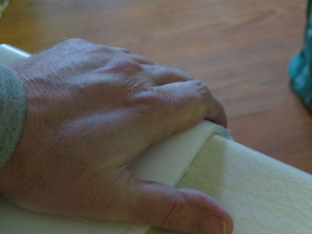
is that the foam core channels should be scored every 3 to 5 mm (perpendicular to the length of the channel) with a sharp razor sufficient to pierce through the paper cover layer of the *CONCAVE* side. This allows the compressive forces felt by the paper to be relieved when bending the channels on the preformed curved surface. If you score the convex side, the bending will break it apart. A good way to precurve it is to lay it on soft carpet after scoring and roll a 3 in to 5 in dia object like a large cardboard tube, a can, etc on the channel slowly back and forth to curve it.
Otherwise, you are spot on! I would ask Cal to link this particular post to his first post as a "Quick Start Guide"
Cheers and happy hot gluing!
X
Great summary! You really did read the whole thread - wow! One important thing to add to the "Construction" section:
The preferred method of construction is to hot glue channel walls to the back baffle, following the pre-marked spiral path, from the middle to the outside edge, taking care to ensure that the junctions are sealed. Hot glue grabs well in a few seconds and allows a short time for adjustment of the channel walls. It helps to pre-form the foam core by bending it around some convenient edge, such as a counter-top, and also if slits approximately 3mm (1/8”) apart or less are cut on the inside faces of small-radius curves.
is that the foam core channels should be scored every 3 to 5 mm (perpendicular to the length of the channel) with a sharp razor sufficient to pierce through the paper cover layer of the *CONCAVE* side. This allows the compressive forces felt by the paper to be relieved when bending the channels on the preformed curved surface. If you score the convex side, the bending will break it apart. A good way to precurve it is to lay it on soft carpet after scoring and roll a 3 in to 5 in dia object like a large cardboard tube, a can, etc on the channel slowly back and forth to curve it.
Otherwise, you are spot on! I would ask Cal to link this particular post to his first post as a "Quick Start Guide"
Cheers and happy hot gluing!
X
Done.I would ask Cal to link this particular post to his first post as a "Quick Start Guide"
Hey there XRK971
That's pretty much what I had in mind when I wrote "It helps to pre-form the foam core by bending it around some convenient edge, such as a counter-top, and also if slits approximately 3mm (1/8”) apart or less are cut on the inside faces of small-radius curves."
But you've expressed it better, and I'd be happy to edit my post so that it was clearer - except that I don't know how. Clearly it's possible, since Cal Weldon has edited post #1 to include a link to my post (I'm flattered, BTW; thank you). Can you enlighten me about how to edit my post?
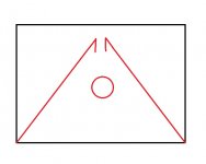
And do you think my suggestion about a front-horn, rear-chamber design, which seems a logical consequence of a couple of the other posts (yours about a larger chamber and Cal's about a flowerpot - which seemed as though it might be a bit fragile, so I thought of a recessed front horn) made any sense? I've included a sketch.
Paul
That's pretty much what I had in mind when I wrote "It helps to pre-form the foam core by bending it around some convenient edge, such as a counter-top, and also if slits approximately 3mm (1/8”) apart or less are cut on the inside faces of small-radius curves."
But you've expressed it better, and I'd be happy to edit my post so that it was clearer - except that I don't know how. Clearly it's possible, since Cal Weldon has edited post #1 to include a link to my post (I'm flattered, BTW; thank you). Can you enlighten me about how to edit my post?
And do you think my suggestion about a front-horn, rear-chamber design, which seems a logical consequence of a couple of the other posts (yours about a larger chamber and Cal's about a flowerpot - which seemed as though it might be a bit fragile, so I thought of a recessed front horn) made any sense? I've included a sketch.
Paul
An externally hosted image should be here but it was not working when we last tested it.
Sorry I missed you calling it slits. To me that sounds like cutting through it where scoring or just piercing surface of paper is how I would have said it. You can only edit a post after 30min if you are the thread starter and it is the first post or if you are a moderator like Cal is.
Your front horn with back chamber idea is pretty cool - give it a try but don't make the bake chamber too big. You can use your formula to calculate cutoff frequency.
Your front horn with back chamber idea is pretty cool - give it a try but don't make the bake chamber too big. You can use your formula to calculate cutoff frequency.
Your writing, X's idea, my implementation - teamwork.(I'm flattered, BTW; thank you)
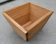
I am thinking of the flower boxes made from red cedar. I keep forgetting they're not available everywhere. It's a very common wood around here. It's like it grows on trees. This one here looks to be hand split and resawn on the ends. Not perfect but that's the idea.Cal's about a flowerpot - which seemed as though it might be a bit fragile
Attachments
Member
Joined 2009
Paid Member
It should work and the sharp edges will filter the mids and highs out better. This design does not have the dual length horns so will not be as smooth in response. Should work though given you use some math to calculate the expansion and length needed. Combined with chamber volume and throat gap.
... Pics below (you can see them hanging in the background of the last pic if you look close).....take care!!!
Great work!
I was looking for a while at the last picture and, surprisingly (or not) the cornu's were spotted last.
By the way, speaking of photos, I always enjoy watching the background of photos, because of what's there-is real, natural, unadjusted, while the subjects on the forefront are "adjusted" and "unnatural" , cheese-freeze-like
Last edited:
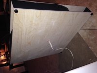
So, I just finished the first of two cornus and I'm pretty sure I messed up. I'm getting nowhere near the copious amounts of bass that probably requires stuffing to attenuate. Quite the opposite, I'm just barely getting enough, even with the speaker stood halfway up the opposite wall. I believe I didn't get the channels sealed enough on the baffle (that I added last). I initially hoped getting it good with adding a few, thin pieces of wood at the mouths and in the chamber and screwing the halves together using them. After that failed, I tried sealing it up with wood glue but I think it's just not good enough.
Anyone have any tips on rectifying this? The front and back are sturdily glued to the channels, but maybe not everywhere. It's like I can hear the bass energy getting sucked out by the movement of the foamboard.
Anyone have any tips on rectifying this? The front and back are sturdily glued to the channels, but maybe not everywhere. It's like I can hear the bass energy getting sucked out by the movement of the foamboard.
That's too bad. Air leaks will kill any bass - it's like leaky pads on a flute, can't hit the low C.
If it's all made of foam you can surgically poke some "windows" in the back to access the channels and add more glue like caulking. Glue to windows baxk once done. Might just have to start all over. Make sure your foam channel is of uniform width. That is what makes a good deal when you cap it off.
If it's all made of foam you can surgically poke some "windows" in the back to access the channels and add more glue like caulking. Glue to windows baxk once done. Might just have to start all over. Make sure your foam channel is of uniform width. That is what makes a good deal when you cap it off.
Yeah, starting over is always an option, I guess. A bit bummed since I started this one this spring but only got around to finishing it now, so it seems like a monumental project. Also, I could only get a hold of 3mm foam core at the time, so I built it with two layers of it, for a total of 6mm, so it's close to twice the normal work, I guess. Maybe getting hold of 5mm and making more even cuts would help. Quite hard to make sure of that before it's too late, though.
- Home
- Loudspeakers
- Full Range
- Ever think of building a Cornu Spiral horn? Now you can!