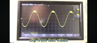
Comparing the transient correction of the circuits above.
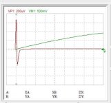
A generator of 10khz 1v is placed in series with the output and the transient of the envelope is considered of the residual. The purpose of the error corrector is to flog the chip with a higher derivative impulse at the start of the envelope to make it reach the steady state faster. This is the chip alone.

With wideband error amplifier in post2 it becomes this.

The return of the accelerating impulse is due to 2 pole correction.
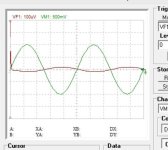
This is that of Modulus86.

If it is opposite phase because of 2 integrators where each needs to be accelerated but no any accelerating impulse. This makes it worse than stand alone.
This is the Yewen with wide band error amp.

Great accelerating pulse but -90°phase shift because the wideband is inverting, I think this is not good.
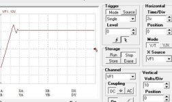
This is the original Yewen with integrator.

Similar to Modulus86 but with accelerator pulse, is it sufficient for both integrators?
A generator of 10khz 1v is placed in series with the output and the transient of the envelope is considered of the residual. The purpose of the error corrector is to flog the chip with a higher derivative impulse at the start of the envelope to make it reach the steady state faster. This is the chip alone.
With wideband error amplifier in post2 it becomes this.
The return of the accelerating impulse is due to 2 pole correction.
This is that of Modulus86.
If it is opposite phase because of 2 integrators where each needs to be accelerated but no any accelerating impulse. This makes it worse than stand alone.
This is the Yewen with wide band error amp.
Great accelerating pulse but -90°phase shift because the wideband is inverting, I think this is not good.
This is the original Yewen with integrator.
Similar to Modulus86 but with accelerator pulse, is it sufficient for both integrators?
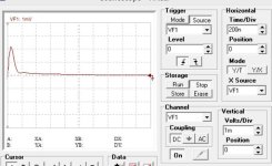
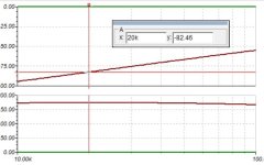
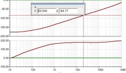
This what Yewen error corrector has reached.
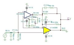
It has -82db@20khz, very good error transient but has an overshoot because I don't know how to limit the correcting frequency limit.

The clipping for now is controlled by zeners. This works well if used with fixed power supply. It will not work with sagging supply. The offset is adjusted by the AD829.
It has -82db@20khz, very good error transient but has an overshoot because I don't know how to limit the correcting frequency limit.
The clipping for now is controlled by zeners. This works well if used with fixed power supply. It will not work with sagging supply. The offset is adjusted by the AD829.
Attachments
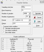
To measure the distortion reduction of the Yewen error corrector, I added two generators of 2khz 0.2v and 3khz 0.2v to simulate the distortion of LM3886 inverted mode, to be 0.01% for 28.5W 8 ohm.
With error corrector it falls down to near the same as the generators distortion of 5.7E-6%.
The distortion of AD829 is implemented.

With error corrector it falls down to near the same as the generators distortion of 5.7E-6%.
The distortion of AD829 is implemented.
Attachments
Last edited:
To measure the distortion reduction of the Yewen error corrector, I added two generators of 2khz 0.2v and 3khz 0.2v to simulate the distortion of LM3886 inverted mode, to be 0.01% for 28.5W 8 ohm.
With error corrector it falls down to near the same as the generators distortion of 5.7E-6%.
The distortion of AD829 is implemented.
View attachment 1268455

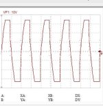
The clipping is controled by 2 zener diodes to assure smooth clipping.and also how the circuit performs as it recovers from clipping.
ToTom
See post 17.
Right. But have you tested it in the lab as function of power supply voltage or does this project only exist in the simulator?
Simulation projects are fun and all, but what I've been trying to tell you for the past many posts is that reality is often different than the simulation results with the LM3886. At least that's been my experience in my last ten years of working with that IC. Maybe your experience is different.
Tom
Simulation projects are fun and all, but what I've been trying to tell you for the past many posts is that reality is often different than the simulation results with the LM3886. At least that's been my experience in my last ten years of working with that IC. Maybe your experience is different.
Tom
It will take me few hours to mount this circuit as I already have several LM3886 mounted ready to run and I already have in drawer AD829 to mount on 8dip adapter. Next week when I return back home, I'll try it to hear if it sounds better than the chip+MOSFET composite.
https://www.diyaudio.com/community/threads/chip-amp-mosfet-composite.403832/#post-7540229
I will try also to parallel 2 lm3886 in open loop mode as it has high impedance output according to its discreet model with adjusting the positive input attenuator, maybe it works.
I need to check for the startup and off plops which might need a solution.
Without the zeners, when it clips the signal becomes square wave.
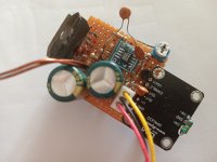
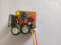
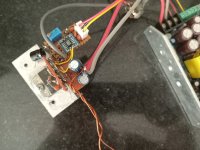
I built the Yewen corrector circuit, see picture bellow. As I am in the mood, I will build also a simplified version of the non inverting type with AD829 in integrator instead of wide band to compare apple to apple. This version has -70db@20khz instead of -88db which is the same with lm3886+2n7000. Thus I will be able to determine comparatively the best one to retain as Modulus clone.

To remind that the Yewen is -82db and Modulus86 is -65db.
To remind that the Yewen is -82db and Modulus86 is -65db.
Attachments
Last edited:
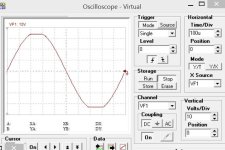
With better adjustments, I get -83db@20khz. I found a simple way for saturation, a resistor with a pair of diodes across the unity follower in the AD829. Probably the same can work for the Yewen version.

Attachments

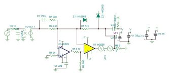
I made an optional clean saturating circuit to fit with analog sagging supply. To understand how it works, swipe the collector and emitter of the first transistors. When the output reaches to a certain voltage determined by the supply - zener 4.6v, the transistor conducts current to make the input signal to be limited, by this it will presaturate adapting to the supply. As the output voltage can swing to opposite supply rail, the emitter base voltage of about 7v gets exceeded and it can be 80v. Instead of using high voltage diode in series and reduce the high unnecessary gain, I swept the collector and emitter.
The circuit is ready to be tested.

The circuit is ready to be tested.
Attachments

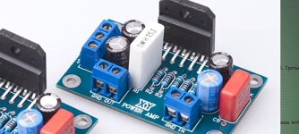
This is a successful subtracting error corrector. It transformes the lm3886 into high resolution grandiose sound. The module can be added any existing amplifier as a Gainclone to convert it into Modulus clone. I need to find a procedure to adjust.
I will start the PCB design which requires 4 layers. I have never designed any PCB, I will ask help on a brotherly website of EEVBLOG.
I will start the PCB design which requires 4 layers. I have never designed any PCB, I will ask help on a brotherly website of EEVBLOG.
Attachments
- Home
- Amplifiers
- Chip Amps
- Error Corrected Chip Amplifiers, aka Modulus Clone