This circuit is a natural variant of subtracting error correction but included in the feedback. Instead of subtracting the error, it divides it by NFB.
https://www.diyaudio.com/community/threads/subtracting-error-correction.408153/post-7578125
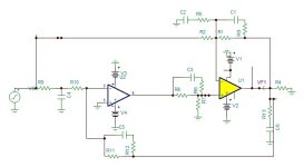
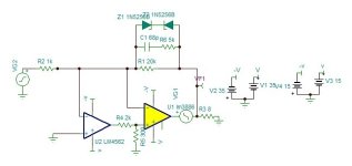
An error correcting amp feedback only the error found by the difference of the input and the weighted output. The advantage over the composite type, the power chip receives directly the input signal without extra layer and the opamp functions at very low levels which doesn't require super low distortion opamp.
I should rather say wide band error amp instead of opamp because it must amplify the error without integrating it. The difference the error amp sees, is the same what the power amp sees, as the power chips are integrators in open loop, if the error amp also integrates the same input, it will become back an image of the output signal. To keep at high gain all the audio band, it needs 2 pole compensation for stability.
This type of amps have two independent stability character, the error feedback loop and the error correction frequency. If higher frequencies than the power chip are asked to get corrected, the chip amp will decrease its phase margin, this why the error amp receives the input via a low pass filter.

I use the AD829 wide band opamp which can have its gain bandwith adjusted. This amp doesn't need servo as the error receives the DC component of the output without attenuation. The slight offset can be adjusted by the opamp offset adjust, not implemented on the model, so I adjusted by R7.
The LM3886 has OLG@20khz of 50db. With 26db CLG, only 24db NFB is left. With this error corrector 80-100db is possible.
https://www.diyaudio.com/community/threads/subtracting-error-correction.408153/post-7578125
An error correcting amp feedback only the error found by the difference of the input and the weighted output. The advantage over the composite type, the power chip receives directly the input signal without extra layer and the opamp functions at very low levels which doesn't require super low distortion opamp.
I should rather say wide band error amp instead of opamp because it must amplify the error without integrating it. The difference the error amp sees, is the same what the power amp sees, as the power chips are integrators in open loop, if the error amp also integrates the same input, it will become back an image of the output signal. To keep at high gain all the audio band, it needs 2 pole compensation for stability.
This type of amps have two independent stability character, the error feedback loop and the error correction frequency. If higher frequencies than the power chip are asked to get corrected, the chip amp will decrease its phase margin, this why the error amp receives the input via a low pass filter.
I use the AD829 wide band opamp which can have its gain bandwith adjusted. This amp doesn't need servo as the error receives the DC component of the output without attenuation. The slight offset can be adjusted by the opamp offset adjust, not implemented on the model, so I adjusted by R7.
The LM3886 has OLG@20khz of 50db. With 26db CLG, only 24db NFB is left. With this error corrector 80-100db is possible.
Attachments
Last edited:
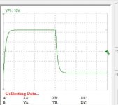
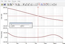
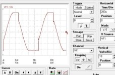
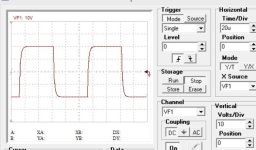
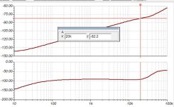
I reduced the input impedances to get the noise halved. The total error correction of the circuit, power chip +opamp @20khz is 88db vs 56db for the subtractor and 24db for 3886 stand alone all for the gain of 26db.

Notice the phase of the error, it remains about 90°all the audio band in first order integration by the power chip.

Notice the phase of the error, it remains about 90°all the audio band in first order integration by the power chip.
Attachments
Last edited:
As the power chip needs to receive directly the input, in current mode, will be in the negative input, the required topology is that of Modulus86 you find it bellow without values.
"Not to infringe the copyright".
The opamp need to be replaced with CFA type , as AD844 for example.
The problem is how to feed the same input current to both amps. An answer is to use a current mirror that feeds the copy to the power and the undistorted to the error.
"Not to infringe the copyright".
The opamp need to be replaced with CFA type , as AD844 for example.
The problem is how to feed the same input current to both amps. An answer is to use a current mirror that feeds the copy to the power and the undistorted to the error.
Attachments
$125/hour for DIY consulting. But maybe I should increase it...I read several years ago, he charges his services $150 an hour.
") That's about what my auto mechanic charges and I think my services are worth at least as much. I charge more for commercial consulting where the expectations are higher and the risks higher too.
That's about what my auto mechanic charges and I think my services are worth at least as much. I charge more for commercial consulting where the expectations are higher and the risks higher too.I think my boards and Kit are fairly priced on the cost vs performance ratio, so my interest in helping someone create a copy of it is pretty limited. That said, I'm certainly happy to help you by providing some input on what to measure and look for in real life. Simulation only goes far with the LM3886 model.
I'm curious what data you're looking for.
Tom
That's my feeling about simulation generally......Simulation only goes far with the LM3886 model.
I'm curious what data you're looking for.
Tom
I'd be more impressed with a simple scheme to make a modest improvement to the 3886, backed up with some measurements.
Preferably over a range of frequencies, single levels, load impedances and phases.
A simulator is just a calculator. Garbage in, garbage out. On the other hand, if you have good simulation models, like the device models we had when I was working at National Semiconductor and TI, the simulation results are generally spot on. Even our phase noise simulations were incredibly close to reality, which is remarkable considering the complexities of those. It would be impossible to design analog ICs without a strong correlation between simulation output and reality.That's my feeling about simulation generally.
The LM3886 model is more of what I'd call a behavioural model. It's pretty accurate as a small signal model, but it does show some weakness for large signal behaviour. And I always get a chuckle when I see people try to simulate anything power supply related with the LM3886 model as that isn't covered by the model.
Keep in mind that the LM3886 model was like created in the early/mid 1990s when the LM3886 came out. Computer simulation was a different game then. We were usually pretty happy if Windoze 3.1 stayed running for more than an hour without crashing.
If you could flatten the THD+N vs frequency so the HF THD becomes inaudible I bet you could get a pretty good amp.I'd be more impressed with a simple scheme to make a modest improvement to the 3886, backed up with some measurements.
Tom
In principle, it's a fine idea to add some clever correction using a low power faster amp.
Maybe a review of Quad Current Dumping amps and other related schemes is in order?
I vaguely recall reading a book mentioning a few amps.
Sandman is a name in this field, a google search on that returns to this forum.
Or, I could be completely missing what the OP is thinking.
Maybe a review of Quad Current Dumping amps and other related schemes is in order?
I vaguely recall reading a book mentioning a few amps.
Sandman is a name in this field, a google search on that returns to this forum.
Or, I could be completely missing what the OP is thinking.
The purpose of this circuit is to higher the NFB of a chip amp to reach 70db@20khz without adding a layer in front of the chip.
I can reach 70db with just adding a MOSFET transistor in composite.
https://www.diyaudio.com/community/threads/chip-amp-mosfet-composite.403832/
Why 70db?
Chip amps are power opamps, they are integrators through the whole audio band. The opamps of high quality dedicated for audio has 70db@20khz NFB at unity gain because the open loop 90°phase shift to closed loop near 0° shift time depends only on the NFB.
Adding an extra layer infront of the chip amp which already has multistage, is similar to over proccesed food. The sound becomes less live, goes to backstage.
If the purpose would have been to get lower distortion numbers, I would have replaced the single ended MOSFET with an LTP+ current mirror and loose the tube sound character.
Can we express that as a transfer function for the open loop amp and a transfer function for the feedback?
What is the transfer function of the closed loop amp we desire? As close as possible to a flat linear gain of ndB or not?
Would you like a power amp which is a perfect opamp or not?
What is the transfer function of the closed loop amp we desire? As close as possible to a flat linear gain of ndB or not?
Would you like a power amp which is a perfect opamp or not?
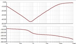
This is the OLG of LM3886.

It has 50db@20khz and 3db shy to 80db@1khz. ST micro. Chips have 80db@1khz.
As these chips require over 26db CLG for stability, then the curve goes downward to reach at 24db@20khz.
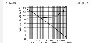
Bellow is the OLG of LM4562 audio dedicated opamp. It has 90db@1khz and over 70db@20khz. This type of opamps are compensated for unity gain CLG. They are perfect unity gain audio high to low impedance buffers to be used as mixers, Sallen-Key filters etc.
This is the required LG that the power chip needs to get, with 26db gain,it needs 96db@20khz of OLG. In other words it needs 46db extra gain from a wide band amplifier.
It has 50db@20khz and 3db shy to 80db@1khz. ST micro. Chips have 80db@1khz.
As these chips require over 26db CLG for stability, then the curve goes downward to reach at 24db@20khz.
Bellow is the OLG of LM4562 audio dedicated opamp. It has 90db@1khz and over 70db@20khz. This type of opamps are compensated for unity gain CLG. They are perfect unity gain audio high to low impedance buffers to be used as mixers, Sallen-Key filters etc.
This is the required LG that the power chip needs to get, with 26db gain,it needs 96db@20khz of OLG. In other words it needs 46db extra gain from a wide band amplifier.
Attachments
I may have a good solution for you.Just give me tip how this design could be converted to a cfa / current driven amp.
@ihan whispered me a different type of error corrector of Modulus type but far faaar simpler. It is D. Yewen composite published in electronics and wireless world Feb.87.
https://blog.easychipamp.com/
I made a quick essay to find that it is possible to get very easily 74db@20khz NFB.
It can be animated by current input that I need to know what is your max peak level to dimension the I/V transconductance.
PS. I will also charge 125 VD an hour.
https://www.google.com/search?q=dol...id-samsung-ss&sourceid=chrome-mobile&ie=UTF-8
Attachments
Last edited:
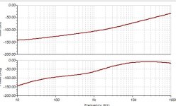
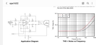
The distortion of this amp is that of the input buffer. To make it best is to use differential in/out ultra low distortion amp the opa1632. Ali sells it all mounted on a board for $2.
This gives the possibility of differential input and also to have this amp bridged.
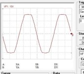
By using AD829 in 2 pole, I have -82db@20khz and -90° phase shift all the audio band.

This gives the possibility of differential input and also to have this amp bridged.
By using AD829 in 2 pole, I have -82db@20khz and -90° phase shift all the audio band.
Attachments
This is simulation stage. It allows to avoid building circuits that doesn't work. It requires a second stage what the French call, "mise au point", to bring it to the goal. Never things go as planed, an inductive component of PCB trace, electromagnetic radiation feedback of the Thiel coil, a PCB leakage in high impedance input, problems that needs to be resoved.Is this all simulation, or have you actually built ?
Patrick
Between conception and realization there is always a gap to fill which is the mission of the technician.
- Home
- Amplifiers
- Chip Amps
- Error Corrected Chip Amplifiers, aka Modulus Clone